Tube end forming defects fall into two families, and the distinction decides the fix. Splitting is a tensile failure, where the material was pulled past its elongation limit. Wrinkling is a compressive instability, where the material was pushed and had nowhere to go. Almost every tube end forming defects case is one of those two, and they respond to opposite adjustments.
That matters because the instinctive fix is usually wrong. A split end does not improve when the operator slows the ram if the material has already run out of stretch. A wrinkled end gets worse when force is added, because the wall was already unstable.
What follows separates the two families, adds the ratio arithmetic that turns a judgement into a number, and sets out the sequence rules that decide whether a part is formable at all.
What Tube End Forming Defects Actually Come From
Every end forming operation loads the wall in a specific direction, and the defect follows the load.
Expansion loads the wall in tension
Expansion pushes a sizing punch into the tube end, increasing the diameter. Wall stress runs hoop-wise, with circumferential tensile strain. When the required expansion ratio exceeds what the material can still stretch, the edge splits.
Reduction loads the wall in compression
Reduction pushes the tube end into a die, decreasing the outside diameter. Now the wall sees axial and circumferential compressive stress, and a thin wall over an unsupported length buckles instead of flowing.
The third family is instability, not strength
Some tube end forming defects are neither tensile nor compressive in origin. They are stability failures: the unsupported length between clamp die and forming die is too long, the die clearance is too generous, or the clamping force lets the tube slide backward mid-stroke. Material strength does not predict them, and adding force makes them worse.
Decision Matrix: One Step, Progressive Steps or Anneal
The choice between a single stroke, progressive steps and an intermediate anneal follows from the ratio rather than from habit.
| Situation | Route to evaluate | Why | What confirms it |
|---|---|---|---|
| Expansion under about 10% on annealed tube | Single stroke, entry taper optional | Well inside typical elongation for annealed stock, so a straight punch often suffices | Sample part with wall check |
| Expansion 10–20% on annealed tube | Single stroke with shallow taper and full lubrication | Taper spreads the strain over the stroke | Inspect edge and seam after 3 parts |
| Expansion above 20%, or seam in the strain zone | Progressive steps, seam moved, or anneal | Each step changes the load path and contact, not the total strain the material must survive | Measured wall plus crack inspection on a sample |
| Reduction under about 10% | Single stroke | Short unsupported span, low compressive load | Sample part, check transition zone |
| Reduction 10–20% on normal wall | Two progressive steps | Shorter span per pass | Check for fold at transition |
| Reduction above 20%, or thin wall | Progressive steps with shorter unsupported length | Buckling risk scales with span | Dimensional check plus visual |
| Any case where the ratio exceeds the material | Anneal between steps or redesign the joint | Restores elongation; design removes the need | Material certificate plus sample |
Those percentage bands are planning figures, not values from any standard, and they should be confirmed on your material before a batch is committed.
A forming window you can plot
Two numbers on one chart decide more than any rule of thumb: the forming ratio the part demands, and the margin the material has left. Plot ratio against material condition and the chart divides into three zones.
Inside the material margin, a single pass with routine tooling is realistic. Close to the margin, a single pass survives only with a shallow taper and verified lubrication. Beyond the margin, the choices are progressive steps, an anneal, or a design change.
The window is a planning aid for tube end forming defects, not a warranty. It tells you where to spend a sample; it does not tell you the part will pass.
Reading the matrix in the right order
- Start from the ratio, calculated from the actual diameters
- Treat certificate elongation as context, not as a pass/fail threshold, since it is a total elongation from a tensile test and the forming ratio is a dimensional change
- Choose the route only after those two numbers are side by side
Reversing that order turns a calculation into an opinion, and opinions about formability are expensive when a batch of tube is already cut.
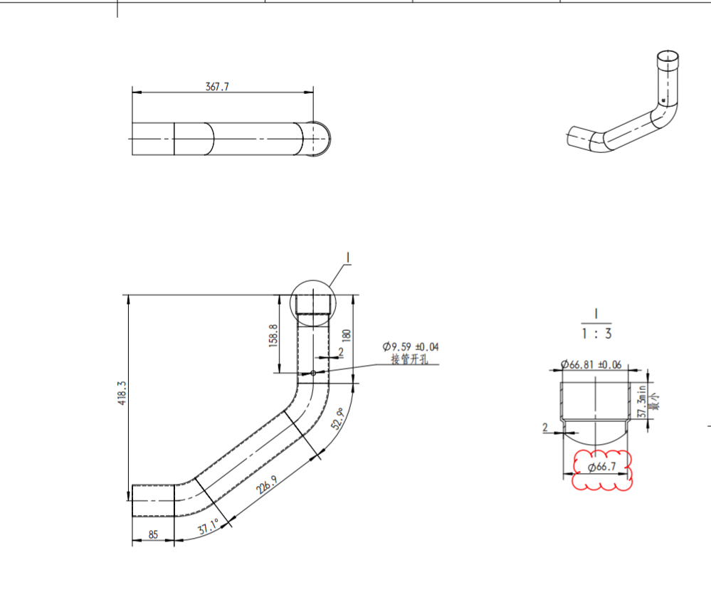
A stainless case: a 62.7 mm bore expanded to 66.81 mm
A production part from our own shop shows what a comfortable ratio looks like on paper and in the part, and it is the kind of record that turns tube end forming defects advice into a verified statement.
- Material: stainless tube, annealed before forming
- Bore before forming: 62.7 mm inside diameter
- Bore after forming: 66.81 mm inside diameter, held to ±0.06 mm
- Expansion achieved: 4.11 mm on diameter, about 6.6% of the original bore
- Tooling: straight sizing punch with no entry taper
- Result: no cracking at the free edge, no wrinkling at the transition
Two details make the case useful. The ratio sits inside single-pass territory for annealed austenitic tube, which is why a straight punch without taper worked here — entry taper matters more as the ratio climbs and the strain needs spreading over a longer stroke. And the part accepts either sequence: expand then bend, or bend then expand. That holds because the expanded zone and the bend transitions do not overlap on this geometry, so work hardening from bending never reaches the forming zone.
What the case does not prove is equally worth stating. Wall thickness at the formed zone was not recorded here, so no thinning figure can be claimed from it, and the drawing geometry that allows both sequences is not the same as a part where the bend sits close to the end. A ratio without a measured wall is half a record, and on a pressure part it is the half that matters.
The Arithmetic That Turns Judgement Into a Number
Two formulas carry most of the decision, and both are simple enough to run at the quotation stage.
expansion % = (D2 − D1) ÷ D1 × 100
reduction % = (D1 − D2) ÷ D1 × 100
Where D1 is the original outside diameter and D2 is the formed diameter.
Wall thinning follows from the same geometry
Expansion thins the wall, and to a first approximation the wall scales inversely with diameter:
Preliminary wall estimate: t2 ≈ t1 × (D1 ÷ D2)
That approximation assumes the wall redistributes uniformly and the length does not change. In practice the formed zone thickens or thins unevenly, tool contact is local, and axial flow varies along the taper, so the number is a preliminary estimate only. It is good enough to decide whether a drawing is worth quoting. It is not good enough to accept or reject a part, and it does not replace a measured wall on a formed sample.
| Case | D1 | D2 | Ratio | Wall change (from 1.5 mm) | Result |
|---|---|---|---|---|---|
| Expansion | 25 mm | 28 mm | 12% | 1.34 mm | 10.7% thinner |
| Expansion | 25 mm | 30 mm | 20% | 1.25 mm | 16.7% thinner |
| Expansion | 25 mm | 32 mm | 28% | 1.17 mm | 21.9% thinner |
| Reduction | 30 mm | 27 mm | 10% | 1.67 mm | 11.1% thicker |
| Reduction | 30 mm | 24 mm | 20% | 1.88 mm | 25% thicker |
Checking a drawing in two minutes
A quick screen catches most impossible drawings before a quotation exists.
- Read the original diameter, the formed diameter and the wall
- Calculate the ratio and the resulting wall at the formed zone
- Compare the calculated wall with the minimum on the drawing
- Ask which condition the tube arrives in, since annealed and cold-worked stock differ
If the calculated wall falls below the drawing minimum before the material is even considered, the part is a design question rather than a process question. Second, a reduction thickens the wall, which is usually welcome, but it also means the finished bore shrinks, and bore-critical parts need that allowance planned in.
Tooling Geometry and Why Taper Matters
Tooling decides the strain path, and the strain path decides the defect.
Punch entry angle
Taper in practice
Entry geometry shows up in the stroke length, and the stroke length shows up in throughput.
- A steep entry completes the form over a short stroke, which raises strain rate
- A shallower taper extends the stroke and spreads the same strain over more material
- A longer stroke costs cycle time, so the trade is defect rate against parts per hour
- Most marginal expansions are lost on entry angle rather than on tonnage
When a tube end forming defects pattern appears only at higher stroke speeds, the taper is usually the variable worth changing first.
Die clearance in reduction
Clearance that is too generous lets the wall deflect outward or inward rather than flowing into the die. Clearance that is too tight raises friction and drags the material. That window is narrow, which is why reduction dies are made for a specific wall range rather than a nominal diameter.
Concentricity and jaw condition
Clamping jaws that are worn or misaligned introduce the one-sided defect pattern described above. Checking jaw condition and alignment belongs in setup, not in troubleshooting.
Lubrication, Wear and Material Flow
Friction is the hidden variable in tube end forming defects, because it changes both the load and where the material goes.
- Apply lubricant inside and outside, since the punch contacts the bore and the die contacts the outside
- Choose a high-pressure drawing lubricant rather than a general-purpose oil
- Re-apply at the interval the tooling demands, not once per shift
- Inspect punches and dies for scoring, because a scored surface drags material into a thin spot
- Replace worn tooling before it produces a defect pattern, since wear shows up as localised thinning first
Worn tooling is a common slow-onset cause, though no published frequency data supports calling it the most common. A new die works, and six months later the same setup produces splits at the same ratio, because the die surface changed rather than the material.
A lubricant schedule that holds up
Lubrication fails in tube end forming defects for a boring reason: it gets applied once and then forgotten.
- Apply inside and outside according to the validated procedure, because the punch and the die contact different surfaces
- Re-apply at the interval the tooling demands, not at the start of each shift
- Use a high-pressure drawing lubricant rather than general-purpose oil
- Wipe and re-lubricate after any interruption, since dried film behaves like no film
A shop that records the re-application interval catches lubrication-caused tube end forming defects before the customer does. Write the interval on the setup sheet, and check it when you change the die.
Sequence Matters: Bending Before or After Forming
Operation order changes the material, and the change is not symmetric.
Bending first work-hardens the material near the bend. If the end forming zone then overlaps the bend transition, the forming pass meets harder material, and the split risk rises. That overlap is common on short parts where the bend sits close to the end.
- Where the formed zone and the bend transition overlap, evaluate forming the end first, subject to clamp space, end geometry and bend order
- Where forming after bending is unavoidable, plan an intermediate anneal
- Where neither is possible, move the transition away from the end by design
- Where the part is welded, consider forming the ends on straight stock before assembly
Where the overlap actually happens
Overlap is a geometry question, and it can be measured rather than argued about.
Measure the distance from the tube end to the start of the bend transition, then compare it with the length of the formed zone. If the two overlap, treat the part as form-first then bend. If they are separated by more than a forming length, either order is viable.
That single measurement explains a class of tube end forming defects that otherwise look random, because the same die and the same material produce good parts on one length and bad parts on another. Where the zones do not overlap — as on the stainless part described earlier, where the expanded end sits well clear of the first bend — either sequence works, and the choice becomes a handling and fixturing decision rather than a metallurgical one. The RFQ checklist captures that distance before a quotation is written.
Splitting in Expansion: Why the Edge Fails First
The two mechanisms below explain the failures the earlier sections were screening for. Read them as reference: each one tells you which adjustment direction applies once a defect has already appeared.
Splitting nearly always starts at the free edge, and it usually starts in one place.
The mechanism
A punch enters, the diameter grows, and the circumference has to increase. Circumference grows proportionally with diameter, so a 20% expansion asks for roughly 20% more circumference, and that material has to come from wall thinning plus stretch. Once the stretch budget is spent, the edge opens.
Why the weld seam is the usual suspect
In welded tube, the seam or its heat-affected zone can become a preferential crack initiation site when its ductility, geometry or surface condition differs from the parent metal. A bead that was not fully scarfed, or a brittle heat-affected zone, will fail in tension before the parent metal does — but a well-made, properly annealed seam often performs like base material. Two controls follow: specify fully scarfed tube for forming, and position the seam away from the area of maximum expansion.
Punch geometry changes the strain rate
A steep entry angle forces the material to deform over a short distance and raises the rate at which strain is applied. A shallower taper spreads the same total deformation across a longer stroke, and that is usually enough to move a marginal part into production.
Wrinkling in Reduction: Why the Wall Buckles
Wrinkling is a structural stability problem, not a strength problem, which is why stronger material does not fix it.
The mechanism
Reduction compresses the circumference, and the wall has to thicken or fold. If the wall is thin relative to diameter, or if the unsupported length is long, it folds at the transition zone instead of flowing into the die.
Four things that decide whether it folds
Wall thickness relative to diameter decides how early the wall buckles. The unsupported length between clamp die and reduction die is set by tooling design, and a longer span folds sooner. Die clearance matters because excess clearance lets material deflect instead of flowing, and clamping force matters because a tube that slips backward folds irregularly at the transition.
Why progressive steps work
Two steps change the load in each pass, and they do not halve the ratio. A 30 mm tube reduced to 24 mm is a 20% reduction overall; split into two passes, the first might run 30 mm to 27 mm (10%) and the second 27 mm to 24 mm (about 11.1%). Each pass sees less compressive load and a shorter unsupported span, which is the mechanism that matters — not an even division of the percentage. Worked reduction examples
Wall arithmetic applies in the opposite direction too, and the numbers show why reduction is easier to control.
| From | To | Reduction | Wall change from 1.5 mm | Note |
|---|---|---|---|---|
| 30 mm | 27 mm | 10% | 1.67 mm | Single stroke on normal wall |
| 30 mm | 24 mm | 20% | 1.88 mm | Two steps preferred |
| 30 mm | 21 mm | 30% | 2.14 mm | Progressive steps with shorter span |
Thickening is usually welcome, and it is also why bore-critical parts need the allowance planned in before the die is ordered. A hole that measured 27.0 mm before reduction will not measure 27.0 mm after it.
The Four Causes Shared by Both Defects
Four factors sit behind both splitting and wrinkling, and checking them costs less than any tooling change.
| Shared cause | How it shows up in expansion | How it shows up in reduction |
|---|---|---|
| Concentricity of tooling | Split on one side only | Local wrinkle and a flat spot on one side |
| Lubrication | Higher tensile load, earlier split | Higher compressive load, earlier wrinkle |
| Tool wear and surface damage | Localised thinning then failure | Drag marks then folding |
| Ram speed and strain rate | Immediate cracking at speed | Buckling before the wall can flow |
Concentricity is the one people skip
If the ram centreline and the clamped tube centreline do not coincide, one side of the tube takes more load than the other. A split on one side during expansion, or a local wrinkle and flat spot during reduction, is one signature worth checking against alignment — and also against wall thickness variation, seam position and local material differences, because those produce a similar one-sided pattern. No parameter change compensates for an alignment error, and the symptom is unmistakable once you look for it: a defect that appears on one side and never the other.
Lubrication works on both sides of the wall
High-pressure drawing lubricant applied inside and outside lowers friction, which lowers the tensile load in expansion and the compressive load in reduction. Dry tooling raises both, which is why a lubrication change can fix a defect that looked like a material problem.
Troubleshooting Tube End Forming Defects
Work down this table before adjusting pressure, because pressure is rarely the cause.
| Symptom | Likely cause | First check | Usual fix |
|---|---|---|---|
| Split at the free edge, all round | Expansion ratio beyond material | Ratio against certificate elongation | Open the ratio, or anneal |
| Split on one side only | Tooling not concentric | Ram to tube centreline alignment | Realign jaws and ram |
| Split along the weld seam | Seam not scarfed, or brittle HAZ | Seam condition and position | Use scarfed tube, rotate seam away |
| Wrinkle at the transition, all round | Unsupported length too long | Span between clamp and die | Shorten span, add support |
| Wrinkle with a flat spot on one side | Clamp slip or misalignment | Clamping force and jaw condition | Raise clamp force, realign |
| Fold that appears mid-stroke | Die clearance too generous | Clearance against wall | Correct die for the wall range |
| Edge tears only at high speed | Strain rate too high | Ram speed setting | Reduce speed, keep taper |
| Defect appears after months of good parts | Tool wear | Punch and die surface | Replace or polish tooling |
Four checks resolve most cases before any parameter is touched:
- Measure the actual wall and diameter of the incoming tube, not the nominal
- Confirm the seam condition and its position relative to the forming zone
- Check runout between ram centreline and tube centreline
- Look at the punch and die surfaces under a light
Inspection and Acceptance of Formed Ends
Formed ends fail inspection for reasons that are easy to write down and easy to forget to specify.
- Formed diameter, measured at the specified section rather than anywhere convenient
- Minimum wall at the formed zone, checked ultrasonically on the finished part
- Length of the formed zone, since a short form changes insertion depth
- Concentricity of the formed end to the tube axis
- Surface condition, with a comparison standard at the station
- Crack indication at the edge and at the seam, however small
Write three figures on the drawing to make acceptance decidable: the formed diameter with its tolerance, the minimum wall at the formed zone, and the length of the formed section. Without those three, acceptance depends on who inspects the part.
A sample validation checklist
A formed sample answers three questions, and all three should be recorded before a batch runs.
- Is there a crack indication at the edge or the seam, checked visually at magnification and with dye penetrant where the part carries pressure
- Is the wall at the formed zone above the drawing minimum, measured ultrasonically against a reading on the unformed tube
- Are the formed diameter, formed length and concentricity inside the stated tolerances
Those three checks turn a trial bend into evidence for tube end forming defects control. Without them, a sample only proves that one part did not fail visibly.
Writing the three figures
Three lines on a drawing remove almost every dispute about a formed end.
- Formed diameter with its tolerance, and the section where it is measured
- Minimum wall at the formed zone, with the method named
- Length of the formed section, since a short form changes insertion depth
Method-level detail for the wall and ovality checks sits in the bent tube inspection guide, and the wall mechanism in the wall thinning during bending reference.
Cost and Selection for End Forming Work
Scrap and setup carry most of the cost of tube end forming defects, and both scale with how far the part sits from the material limit.
| Cost driver | What drives it | Planning note |
|---|---|---|
| Scrap from splitting | Ratio against material elongation | Every point of extra ratio raises the loss rate |
| Setup time | Number of progressive steps | Two steps roughly doubles the setup, not the cycle |
| Tooling | Taper geometry, die clearance range | One die serves a wall range, not a nominal size |
| Annealing | Steps required, furnace access | Adds lead time and changes the delivered condition |
| Machine capability | Stroke control, clamping force, station count | Multi-station machines remove manual re-handling |
Three selection questions decide whether a dedicated end forming machine pays:
- How many operations per end, because a multi-station machine removes handling between steps
- How tight the bore tolerance is, since that decides whether the reduction needs a controlled mandrel
- Whether bending and forming happen in one line, because sequence control is easier when one machine sees both
Single station against multi-station
Handling time against machine cost is the comparison, and the arithmetic is simple enough to do on a quote.
- One operation on one end: a single-station machine with manual handling is adequate
- Two or three operations on the same end: handling between stations usually costs more than the machine
- Mixed families with short runs: changeover time decides more than cycle time
- Bore-critical parts: a controlled mandrel decides the machine specification
Buyers who count handling minutes rather than operations usually reach a different and better answer. Tooling cost belongs in the same comparison, and the pipe bending machine tooling reference covers how dies are scoped. A shop forming expand, bead and flare on a family of parts usually does, because handling between three separate operations costs more than the machine.
What to Send Before an End Forming Quote
Six items decide whether the part is formable, and the first is the one most often omitted.
- Original outside diameter, wall and material condition, with the certificate
- The formed diameter and the operation required: expand, reduce, flare, bead or flange
- Whether the tube is welded, and the seam condition and orientation
- Minimum wall permitted at the formed zone
- Whether bending happens before or after forming, and how close the bend sits to the end
- Quantity and repeat pattern, since that decides single-station against multi-station
A feasibility screen you can run yourself
Before contacting anyone, four questions separate a feasible part from a hopeful one.
- What is the calculated ratio, in percent
- What wall does the geometry leave at the formed zone
- Which condition does the tube arrive in, and does the certificate say so
- Does the formed zone overlap a bend transition
As a result, the conversation with a supplier starts at the technical level where it belongs.
Three diagnoses that are usually wrong
Some explanations sound technical and lead nowhere.
First comes “the material is bad”, which is rare once the certificate and the condition are checked. Second is “the machine is weak” — less often true than the others, but still worth checking against stroke, rigidity and rated forming capacity. Third is “more pressure will fix it”, which almost never holds: pressure worsens wrinkling and does nothing for splitting.
When a tube end forming defects report names one of those three causes, ask which measurement supports it. If there is no measurement, there is no diagnosis.
Two numbers worth keeping on the setup sheet
A setup sheet with two numbers on it prevents most repeat arguments.
Write the calculated expansion or reduction ratio in percent, and the calculated wall at the formed zone in millimetres.
With those two figures written down, a repeat order starts from the same assumptions, and a defect gets compared against a baseline rather than a memory.
Two more habits keep tube end forming defects from returning. Photograph the first good part with a scale in frame, so wall and form length can be compared later without arguing. Keep the rejected sample too, because a defect that nobody kept becomes a story rather than a data point. Both habits cost nothing and settle most reviews in under a minute.
Two quick checks make the tube end forming defects arithmetic concrete. A 1 mm wall at 20% expansion finishes near 0.83 mm, and a 2 mm wall finishes near 1.67 mm. If the drawing calls for 0.9 mm minimum, the first case fails on geometry before the material is even considered. That is the fastest screen for tube end forming defects risk on a new drawing. Run it before the quotation, not after the first batch. Most tube end forming defects reports begin with a part that was never screened, and the screen takes one division. Material selection for the process follows the same logic as bending, covered in CNC tube bending material selection. Skip them and the first batch becomes the feasibility study, which is the expensive way to learn.
How Zhuoran Fits Tube End Forming Work
Zhuoran builds tube end forming machines and the tooling for expanding, reducing, flaring, beading, flanging and notching, and the specification starts from the ratio and the wall rather than from the tonnage.
What the company will not do is promise an expansion ratio without the wall and the temper, because the arithmetic does not care which machine is quoted.
What good end forming looks like
Good tube end forming defects control is quiet in the same way, and it starts with a ratio that is comfortable rather than marginal.
- The ratio sits inside the material with margin, not at the edge of it
- The route uses as few steps as the material allows and no fewer
- Tooling is specific to a wall range rather than to a nominal size
- The sequence accounts for bending before the end is formed
- Defects are caught at the edge and the seam, where they start
Most tube end forming defects that reach a customer were visible at the sample stage. Finding them there costs one tube.
Six rules that prevent most tube end forming defects
In practice, rules beat parameters when a shift changes.
- Measure the tube you have. Ignore the nominal.
- Calculate the ratio. Do not estimate it.
- Match the taper to the ratio. Do not match it to habit.
- Lubricate both faces. Every part.
- Check concentricity at setup. Not at failure.
- Form the end before you bend, when the zones overlap.
None of those rules is technical. All of them are skipped under delivery pressure, which is why tube end forming defects cluster at the end of a rush order.
Run the rules as a checklist before the first part. That catches the split before it costs a batch.
Frequently Asked Questions
What is the difference between a split and a wrinkle?
A split is a tensile failure at the outer edge, caused by asking for more stretch than the material has. A wrinkle is a compressive instability, caused by the wall buckling because it had no support or nowhere to flow. They need opposite fixes.
How much expansion can a tube take?
It depends on the material condition and the wall. Calculate the expansion percentage from the diameters, read the certificate elongation as context, and let a sample on the delivered material decide. There is no universal percentage.
Why does the tube crack along the weld seam?
Not automatically. The seam can be the initiation point when its ductility, geometry or surface differs from the parent metal, and a clean, annealed seam often behaves like base metal. If the bead was not fully scarfed away or the heat-affected zone is brittle, the seam fails in tension before the parent metal. Use fully scarfed tube and rotate the seam away from maximum expansion.
Why does the end wrinkle during reduction?
Compressive buckling. Wall too thin for the span, die clearance too generous, or clamping force too low to stop the tube sliding backward.
Does annealing help?
It helps splitting, because it restores elongation. It does not help wrinkling, which is a support and clearance problem. Annealing also changes the delivered condition, so the buyer agrees to it before the order.
Should the tube be bent before or after end forming?
Where the formed zone overlaps the bend transition, form first. Bending hardens the material, and forming into hardened material raises the split risk.
Reference Sources
- Dural Bend, Tube End Forming Defects: Splitting vs Wrinkling — source for the tensile versus compressive framing, weld-seam initiation, punch taper effect, unsupported-length buckling, clamping and clearance effects, concentricity, lubrication and sequence guidance. duralbend.com
- Telhoo Machinery, Tube End Forming Operations and Machines — operation definitions for expanding, reducing, flaring, beading and flanging. telhoomachinery.com
- ASTM A269, Standard Specification for Seamless and Welded Austenitic Stainless Steel Tubing for General Service — incoming tube tolerances that set the starting wall and diameter.
- ASTM A500, Standard Specification for Cold-Formed Welded Carbon Steel Structural Tubing in Rounds and Shapes — section and tolerance reference for carbon steel tube.
Related reading on tube end forming defects: tube end forming machine selection, tube end forming machines, wall thinning during bending, defect triage for bent tubes, bent tube inspection.