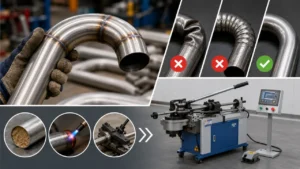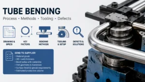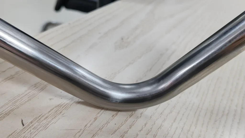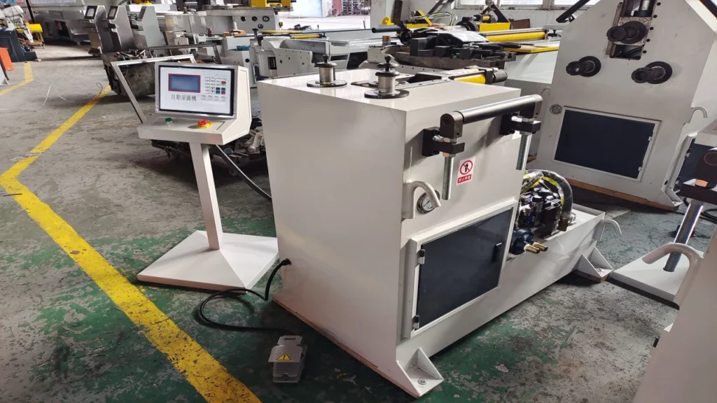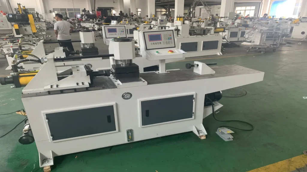
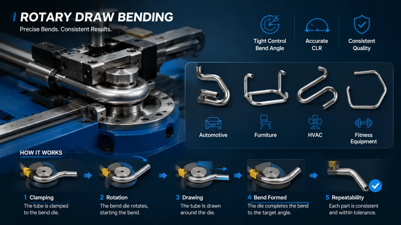
Rotary draw bending forms a tube by clamping it to a rotating bend die and drawing it around a fixed radius. The process gives manufacturers tight control over bend angle, centerline radius and part-to-part consistency. It is widely used for automotive tubing, furniture frames, HVAC assemblies, fitness equipment and other parts that need repeatable bends with a controlled appearance.
Good results depend on more than machine capacity. You must match the tube, bend radius, tooling package and quality requirements before production begins. This guide explains how the process works, how to select tooling and centerline radius (CLR), and how to diagnose common bending defects.
What Is Rotary Draw Bending?
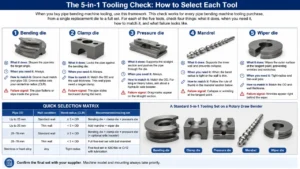
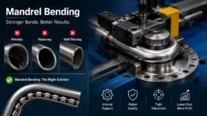
In rotary draw bending, a clamp die holds the tube against a grooved bend die. As the bend die rotates, it pulls the tube around the die profile. A pressure die supports the straight section while the tube advances. For demanding parts, a mandrel supports the tube internally and a wiper die controls material near the inside tangent.
This controlled tooling arrangement makes rotary draw bending suitable for parts that require:
- A defined and repeatable centerline radius
- Accurate bend angles and tangent positions
- Multiple bends in one component
- Controlled ovality, wall thinning and wrinkling
- Consistent production across repeated batches
For programmable multi-bend parts, manufacturers commonly use CNC pipe bending machines. Simpler parts, shorter production runs and operator-controlled feeding may be better suited to NC pipe bending machines.
When Rotary Draw Bending Is Not the Best Choice
Rotary draw bending is designed around a fixed bend die radius. If a component needs a large, sweeping radius rather than a tight elbow, a tube rolling machine may be more practical. The correct process depends on the drawing, tube dimensions, acceptable distortion and required output.
How Rotary Draw Bending Works
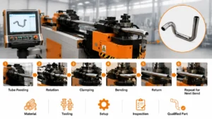
- Load and position the tube. The operator or automatic feeding system places the tube at the required start position.
- Clamp the tube. The clamp die secures the tube against the bend die. Insufficient grip can cause slipping and angle variation.
- Support the tube. The pressure die supports the straight section. A mandrel and wiper die may be added when the wall, radius or finish requirement demands more control.
- Rotate the bend die. The bend die draws the tube around its groove to the programmed angle.
- Compensate for springback. The machine applies a validated overbend or correction value so the released part reaches the target angle.
- Release and advance. The tooling opens, and the tube is removed or repositioned for the next bend.
- Inspect the part. The operator checks angle, position, ovality, wall thickness and surface condition against the agreed drawing and inspection method.
Stable production requires the machine, tooling and program to work as one system. A machine with adequate nominal capacity can still produce poor parts if the grip length is too short, the mandrel position is wrong or the tooling surfaces are worn.
Rotary Draw Bending Tooling
Tooling determines how the tube is held, supported and allowed to flow during the bend. Each component has a distinct job.
| Tool | Primary Function | What to Check |
|---|---|---|
| Bend die | Defines the nominal bend radius and guides the tube around the bend | Groove size, CLR, surface finish and wear |
| Clamp die | Grips the tube and transfers pulling force | Grip length, serration or smooth finish, and slip marks |
| Pressure die | Supports the straight tube and controls material feed | Alignment, contact pressure and lubrication |
| Mandrel | Supports the tube internally to limit collapse and ovality | Type, ball count, size, position and lubrication |
| Wiper die | Controls material at the inside tangent to reduce wrinkles | Tip condition, rake, position and material compatibility |
| Collet | Holds and positions the tube in automatic feeding systems | Concentricity, grip and clearance |
When Are a Mandrel and Wiper Die Needed?
There is no universal CLR-to-diameter threshold that decides the tooling package. Thin walls, small CLR, soft material, demanding ovality limits and cosmetic surfaces all increase the need for internal and tangent support. The supplier should assess the complete tube specification and drawing, then confirm the tooling through a sample bend or production trial.
How to Select Centerline Radius (CLR)
Centerline radius is the distance from the center of the bend to the tube centerline. It is not the inside radius. For a round tube, the approximate relationship is:
Inside radius = CLR − tube outside diameter ÷ 2
The ratio CLR ÷ tube outside diameter is a useful indicator of bend severity. A smaller ratio generally creates more compression on the inside of the bend and more tension on the outside. However, this ratio alone cannot confirm feasibility.
Inputs Required for a Reliable CLR Decision
- Tube outside diameter and wall thickness
- Material grade, temper and mechanical condition
- Welded or seamless construction and weld-seam position
- Required CLR, bend angle and distance between bends
- Allowed ovality, wall thinning and surface marks
- Straight length available for clamping
- Part orientation and dimensional datums
- Annual volume and required cycle time
When the requested radius is aggressive, do not change it without approval. First evaluate whether a different mandrel, pressure-die assist, wiper setup, lubricant or material condition can meet the drawing. If the design remains high risk, compare a larger CLR against the assembly envelope and functional requirements.
Springback and Material Behavior
After the tooling releases the tube, elastic recovery opens the bend slightly. Springback varies with material strength, wall thickness, radius, tooling restraint and batch condition. It should be measured during trials and compensated in the bending program. A single correction value should not be assumed to work across different materials or tube batches.
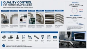
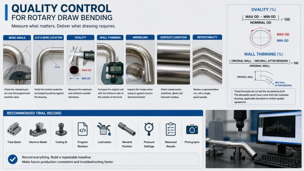
Quality Control for Rotary Draw Bending
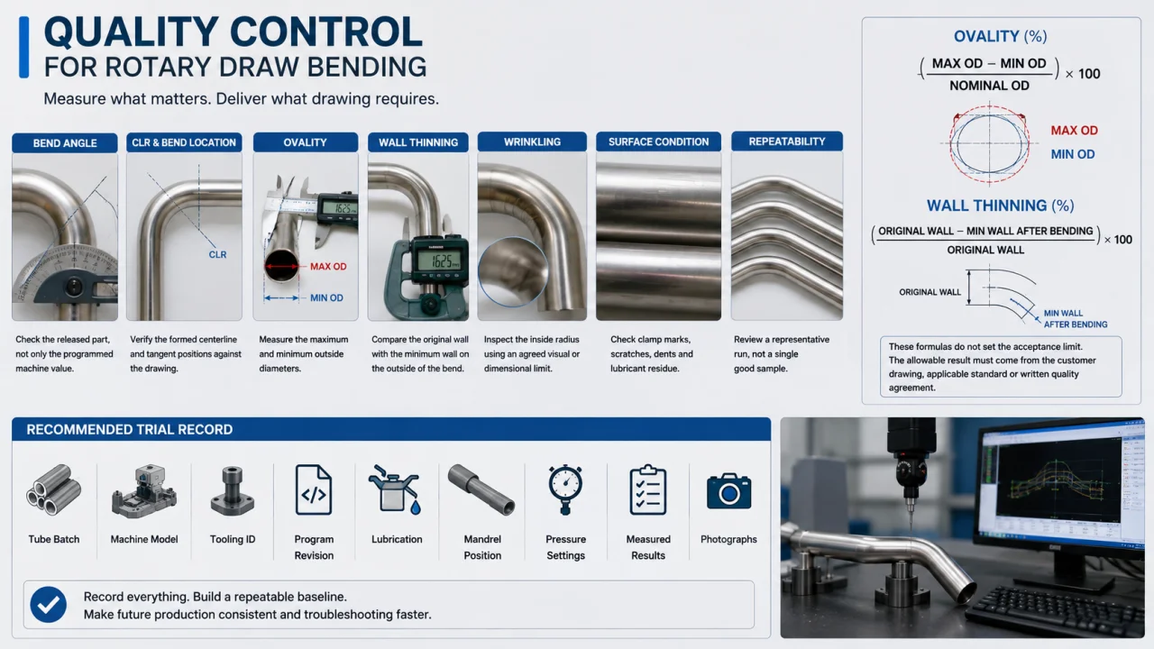
Before accepting a machine or production process, define how each characteristic will be measured. Drawing tolerances, gauges, datum strategy and inspection frequency should be agreed before the trial.
Key Measurements
- Bend angle: Check the released part, not only the programmed machine value.
- CLR and bend location: Verify the formed centerline and tangent positions against the drawing.
- Ovality: Measure the maximum and minimum outside diameters at the specified section.
- Wall thinning: Compare the original wall with the minimum wall on the outside of the bend.
- Wrinkling: Inspect the inside radius using an agreed visual or dimensional limit.
- Surface condition: Check clamp marks, scratches, dents and lubricant residue.
- Part-to-part repeatability: Review a representative run, not a single good sample.
A commonly used ovality calculation is:
Ovality (%) = (maximum OD − minimum OD) ÷ nominal OD × 100
A commonly used wall-thinning calculation is:
Wall thinning (%) = (original wall − minimum wall after bending) ÷ original wall × 100
These formulas do not set the acceptance limit. The allowable result must come from the customer drawing, applicable standard or written quality agreement.
Recommended Trial Record
Record the tube batch, machine model, tooling identification, program revision, lubrication, mandrel position, pressure settings, measured results and photographs. This creates a repeatable baseline for future production and makes troubleshooting faster.
Common Tube Bending Defects and Corrective Actions
| Defect | Likely Causes | Checks and Corrective Actions |
|---|---|---|
| Inside wrinkles | Insufficient tangent support, incorrect wiper position, excessive compression or poor lubrication | Inspect the wiper tip and position, verify mandrel location, review pressure-die settings and confirm lubrication |
| Excessive ovality or collapse | Inadequate internal support, tooling clearance, aggressive CLR or incorrect pressure-die setup | Check mandrel type and size, tooling alignment, pressure support and tube dimensional variation |
| Excessive wall thinning | High outside-wall tension, material variation, small CLR or uncontrolled material flow | Verify material and wall, review pressure-die assist, inspect mandrel setup and evaluate radius feasibility |
| Angle variation | Springback variation, tube slip, inconsistent material or unstable program compensation | Check clamp grip, material batches, tool wear and released-part measurements; then update compensation |
| Surface scratches | Dirty tooling, rough surfaces, trapped chips, wrong clearance or inadequate lubrication | Clean and polish contact surfaces, inspect clearance and use a lubricant compatible with the material and finish |
| Tangent or position error | Incorrect feed, rotation or tooling datum | Verify program coordinates, collet position, tooling zero and part datum strategy |
Change one controlled variable at a time and document the result. Simultaneous adjustments make it difficult to identify the true cause.
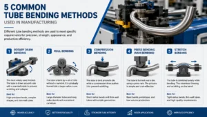
Rotary Draw Bending vs. Other Bending Methods
| Method | Best Suited To | Main Limitation |
|---|---|---|
| Rotary draw bending | Controlled CLR, accurate angles, multi-bend parts and repeat production | Requires dedicated tooling for tube size and radius |
| Roll bending | Large-radius arcs, rings and sweeping curves | Not intended for a tight, fixed-radius elbow |
| Compression bending | Simple shapes and applications with less demanding distortion control | Less control for tight radii and complex multi-bend geometry |
| Press bending | Basic bends where tooling simplicity is more important than cross-section control | Higher risk of flattening and lower geometric control |
What to Send with a Rotary Draw Bending RFQ
A complete RFQ helps the supplier evaluate feasibility, choose the machine and price the tooling accurately. Include:
- 2D drawing and, when available, a 3D model
- Tube OD, wall thickness and dimensional tolerance
- Material grade, temper, finish and welded or seamless condition
- CLR, bend angles, rotation between bends and straight lengths
- Allowed ovality, wall thinning, wrinkles and surface marks
- Required output per shift or annual production volume
- Loading method, automation expectations and available floor space
- Inspection standard and sample-acceptance criteria
If the part is difficult or the specification is incomplete, request a sample bending service before final machine acceptance. A trial using the actual material provides stronger evidence than a capacity chart alone.
Frequently Asked Questions
What is rotary draw bending used for?
It is used for tube and pipe parts that need a controlled bend radius, accurate angle and repeatable geometry. Typical applications include vehicle tubing, furniture, HVAC assemblies, fitness equipment and structural frames.
What does CLR mean in tube bending?
CLR means centerline radius. It is measured from the center of the bend to the centerline of the tube. It differs from the inside radius shown at the inner surface of the bend.
Does every rotary draw bend need a mandrel?
No. The need for a mandrel depends on tube size, wall thickness, material, CLR and allowable distortion. Tight radii, thin walls and strict ovality requirements usually need more internal support, but the final choice should be proven through a trial.
Why does a tube wrinkle on the inside of a bend?
The inside wall is under compression. Wrinkles can result from inadequate wiper or mandrel support, incorrect tooling position, unstable material flow or poor lubrication. Inspect setup and tooling condition before changing the part design.
How is springback controlled?
Springback is measured on released sample parts and compensated through overbend or program correction. Because it varies with material and process conditions, the correction should be validated for the actual tube batch and tooling setup.
Can one bend die produce different radii?
A standard fixed-radius bend die is made for a specific nominal CLR and tube size. Producing a substantially different radius normally requires another bend die or a different forming method.
What should be checked during machine acceptance?
Run the actual material and inspect bend angle, position, ovality, minimum wall, wrinkles, surface condition and repeatability. Confirm cycle time, tool-change procedure, program storage, safety functions and the agreed production quantity.