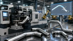

Bent tube inspection fails for a process reason far more often than a measurement reason. The drawing asks for a tolerance and nobody wrote down how it will be checked, so the part gets measured three ways by three people and one of them rejects it. The argument that follows is rarely about precision. It is about which characteristic was specified and which method was agreed.
What follows maps each characteristic of a bent tube to a method that can actually prove it, sets out where a fixture beats a measuring machine and where it does not, and shows what belongs on the drawing so acceptance stops being an opinion.
What Bent Tube Inspection Has to Prove
Bent tube inspection has one job. Show that the part will assemble and perform. Everything else is bookkeeping around that job.
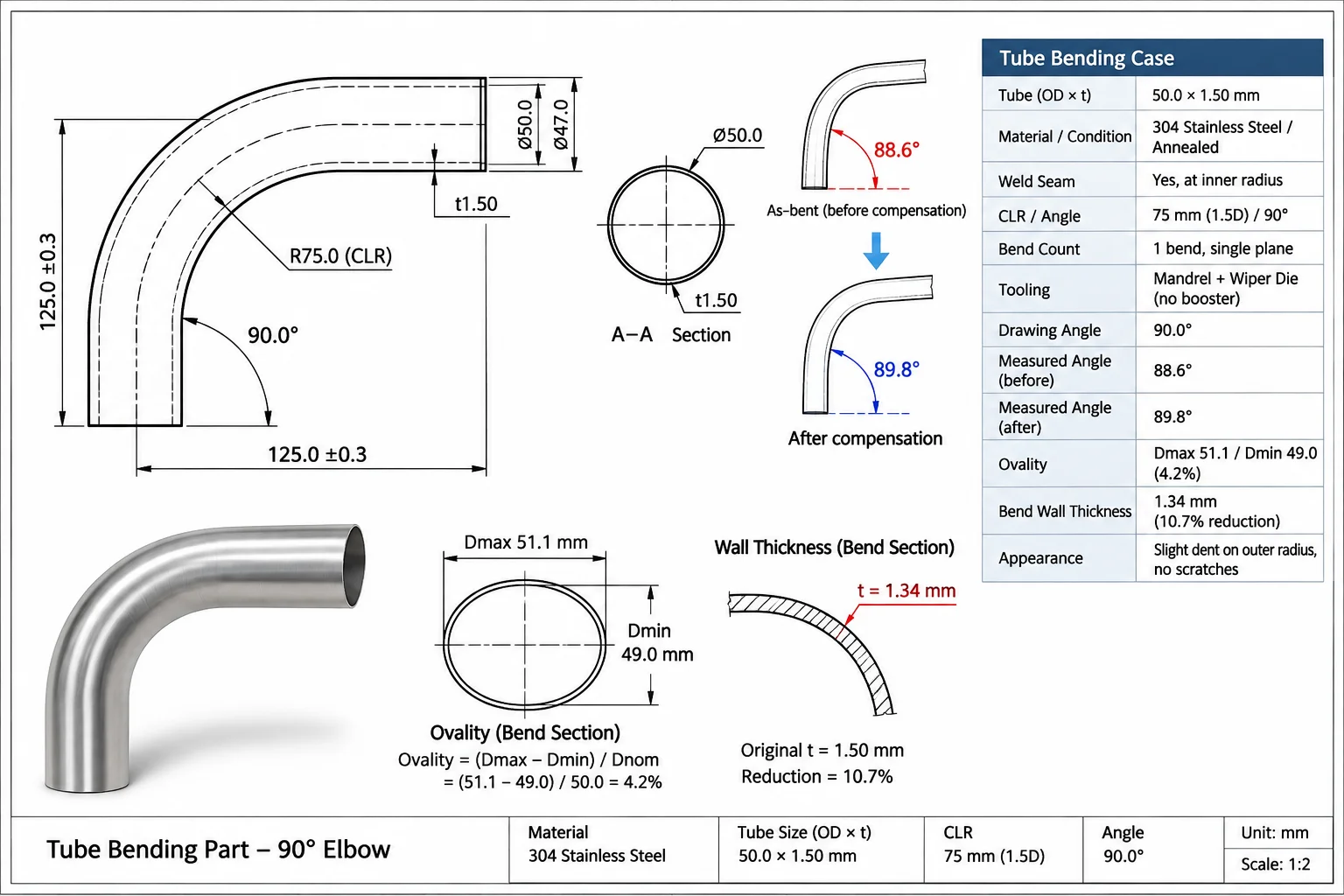
The three questions a part has to answer
- Does it fit the mating parts, in the position the design intended
- Does it carry its load or its pressure without failing where the bend weakened it
- Does it look right where a customer will see it
Each question maps to different characteristics and different methods, and conflating them is how inspection becomes expensive without becoming useful.
What inspection cannot prove
In practice, a dimensional check does not prove the tube will survive fatigue, and a visual check does not prove the wall is intact. Buying a measuring machine does not solve a specification problem, and rejecting a batch does not fix a process that was never capable. Inspection reports risk. It does not remove it.
The Six Characteristics That Can Fail
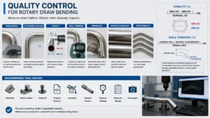
A bent tube has six independent failure categories, and a drawing that names only “bend angle” leaves five of them unmanaged.
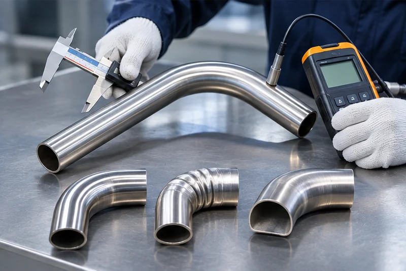
| Characteristic | What failure looks like | Where the decision is made | Method that proves it |
|---|---|---|---|
| Bend angle and plane | Part will not assemble | Machine compensation and program | Fixture, angle gauge plus plane check, CMM |
| Centreline radius | Tangency points shift, whole part is wrong | Die radius | CMM against CAD, or a fixture built to nominal |
| Ovality | Section collapse, flow restriction | Mandrel support and radius | Caliper at the crown, or optical scan |
| Wall at the crown | Thinning that fails later under pressure | Radius against wall thickness | Ultrasonic gauge, or sectioning a sample |
| Surface | Cosmetic rejection, corrosion initiation | Die finish and lubrication | Visual against a comparison standard |
| End condition | Weld fit-up and insertion depth | Cutting and end forming | Squareness check, go/no-go gauge |
The two that actually reject parts
As a result, bend angle and ovality account for most rejections, because both drift with tooling wear and material variation. Wall thinning matters most on pressure-carrying tube, where it is also the hardest to see without a gauge. Treat those three as the sampling set and the rest as first-article checks.
Which characteristic to test first
Order matters when a part is wrong, because fixing one characteristic can disturb another.
- Confirm the angle and plane first, because a wrong angle invalidates every downstream measurement
- Check ovality only after the angle is right, since re-setting the bend changes the section
- Check wall at the crown on the accepted geometry, not on a rejected part
- Judge surface last, because re-bending for angle will re-mark the surface
Following that order saves a setup. Reversing it produces a part that passes three checks and fails the fourth after a correction.
Where the six categories come from
Published quality frameworks for bent tube assemblies group defects into dimensional, surface, weld, springback, material and assembly errors. That grouping is useful because each category points at a different inspection method rather than at a different opinion.
Measuring Bend Angle and Radius Without a CMM
Three tools cover almost all production bent tube inspection, and none of them requires a metrology lab.
Angle gauge plus a plane check
A digital angle gauge on a reference face reads the bend angle quickly and adequately for a single bend. What it does not tell you is whether the bend lies in the correct plane, and an out-of-plane bend passes an angle gauge every time while failing to assemble.
The checking fixture
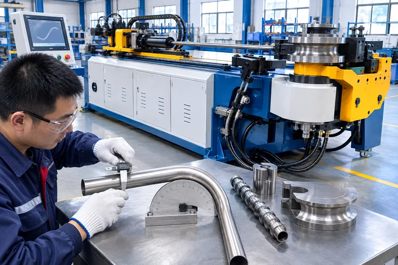
A plate with locating pins for the tube ends and the tangent points checks the part the way it is used. It is fast, repeatable, and it catches plane error because the part either sits in the fixture or it does not.
CMM and optical measurement
Worked example: how angle error accumulates
A single bend tolerance hides a larger truth, and the arithmetic is worth doing before a tolerance is written.
Take a three-bend part with bends of 45°, 90° and 45°, each held to ±0.5°. Each bend is individually acceptable, and the last leg still moves because the errors add geometrically:
| Error at the last leg | Deviation at 300 mm from the final bend | Deviation at 600 mm |
|---|---|---|
| 0.5° | about 2.6 mm | about 5.2 mm |
| 1.0° | about 5.2 mm | about 10.5 mm |
| 1.5° | about 7.9 mm | about 15.7 mm |
Two conclusions follow. First, a tolerance per bend is not the same as a tolerance on the assembly, and a drawing that states one without the other is under-specified. Second, the further a joint sits from the last bend, the more an angle error costs at assembly.
That is why a four-bend fuel line is harder to inspect than a single-bend bracket, even when both carry the same per-bend tolerance.
A coordinate measuring machine with a touch probe or laser scanner captures the geometry and compares it against the CAD model, and optical tube measuring systems do the same faster for complex multi-plane parts. Both tell you the part differs from nominal. Neither tells you which process setting caused the difference.
Measuring Ovality and Wall at the Bend
The ovality formula and why the section matters
Ovality is the difference between the largest and smallest diameter at one section, expressed against nominal:
ovality % = (Dmax − Dmin) ÷ Dnominal × 100
Three worked readings on a 50.0 mm nominal tube show how the same formula produces different decisions:
| Nominal | Dmax measured | Dmin measured | Ovality | Typical reading |
|---|---|---|---|---|
| 50.0 mm | 50.8 mm | 49.3 mm | 3.0% | Comfortable on most visible parts |
| 50.0 mm | 51.5 mm | 48.6 mm | 5.8% | Marginal; depends on the drawing limit |
| 50.0 mm | 52.4 mm | 47.9 mm | 9.0% | Beyond most field-bend limits and clearly rejected here |
Wall behaves the same way once the nominal is fixed. On 1.5 mm stock, a reading of 1.42 mm is 5.3% thinning, and 1.35 mm is 10%. Whether either is acceptable depends on the minimum wall the drawing states, which is exactly why a percentage reduction is a weaker specification than an absolute figure.
The formula is trivial. What matters is where it gets applied. Measure at the crown of the bend, across two opposing points. A reading taken on the straight almost always passes, because the straight never deformed.
Why the measurement point is the whole argument
- At the crown, ovality reflects mandrel support and radius
- Near the tangent point, it reflects how the bend started
- On the straight, it reflects nothing and proves nothing
A drawing that says “ovality 8%” without naming the section has specified a number rather than a requirement. When you see that on a drawing, ask which section was intended before you measure anything. Section behaviour in more depth sits in ovality in bent tube.
Wall at the crown
Wall behaviour follows the strain: the outer wall thins and the inner wall thickens, so only the outer face matters for acceptance. An ultrasonic gauge at the crown, referenced against a reading on the straight, gives a usable number without cutting the part. Sectioning stays a first-article and process-validation tool. The mechanism is covered in wall thinning during bending.
State a minimum wall on the drawing rather than a percentage reduction. A percentage invites an argument about which nominal dimension was meant, and that argument has no technical answer.
Surface Marks and the Cosmetic Boundary
Surface judgement causes more disputes in bent tube inspection than any dimensional check. What counts as acceptable depends on where the mark sits and who is looking.
Three things make surface acceptance decidable:
- A comparison standard, physical or photographic, kept at the inspection station
- A zone map on the drawing that separates visible, coated and hidden areas
- A written distinction between a mark that will be covered and one that will not
Calibrated lighting and magnification belong in the method description. Under a bench light a tool mark looks different from the same mark under a bright directional lamp, and two inspectors using different lighting will disagree indefinitely.
A clamp mark on a powder-coated bracket is not the same defect as the same mark on a polished stainless handrail. Writing one criterion for both guarantees a dispute.
Which Non-Destructive Test Fits Which Defect
That said, non-destructive testing is often specified as a habit rather than as an answer to a question. Each method detects a specific class of defect, and using the wrong one produces a clean report that proves nothing.
| Method | What it detects | Where it earns its cost |
|---|---|---|
| Visual with magnification | Surface cracks, weld appearance, finish defects | Every part, every batch |
| Dye penetrant | Surface-breaking defects in any material | Weld toes and bend surfaces on non-magnetic grades |
| Magnetic particle | Surface and near-surface discontinuities in ferromagnetic steel | Carbon and low-alloy steel welds |
| Ultrasonic | Internal cracks, voids, delamination, wall | Wall verification and internal soundness |
| Radiographic | Internal porosity, inclusions, weld penetration | Weld quality on critical joints |
| Eddy current | Surface and near-surface cracks in conductive material | Tube surfaces where contact is impractical |
| Leak test | Pressure boundary defects | Any part that will hold fluid or gas |
When non-destructive testing is actually required
Ask what failure the test is meant to prevent:
- Pressure boundary: leak test, plus wall verification at the bend
- Structural or safety part: surface method plus weld examination
- Visible or cosmetic part: visual and finish only
- Fluid or fuel line: cleanliness and bore inspection, often overlooked
A test that does not map to one of those four answers is being bought to satisfy a checklist rather than a risk.
Writing a test into the drawing
A test that is not written down is a test that will be dropped under delivery pressure.
- Name the method, not the intent: “dye penetrant per the drawing note” beats “weld inspected”
- Name the extent: full length, weld toes only, or a stated sample
- Name the acceptance basis: which defect classes reject, and which are recorded only
In practice, the third item is the one that prevents arguments, because it separates what must be fixed from what must be noted. Without it, every inspector applies a different threshold and every batch gets a different answer.
A bent tube inspection checklist
A one-page checklist keeps a shift consistent, and it takes less time to use than to argue about.
- Caliper resolution 0.02 mm is enough for ovality on most tube
- A micrometer at 0.001 mm suits wall checks on thin stock
- An ultrasonic gauge at 0.01 mm suits wall where the part cannot be cut
- Angle gauge to 0.1° suits a single bend; a fixture suits a family
- Comparison standard present at the station before surface is judged
Five lines, five tools, and one rule: if a tool is not on the list, the measurement it produces does not count.
Instrument capability in plain terms
Resolution and accuracy are different things, and buyers often treat them as the same.
A caliper reading to 0.02 mm is fine for a 50 mm tube with a 3% ovality limit, because the limit sits at 1.5 mm of diameter variation. A micrometer reading to 0.001 mm is overkill for the same part and appropriate for 1.5 mm wall where 5% thinning equals 0.075 mm. Matching the tool to the limit is what keeps bent tube inspection proportionate.
Cost and Selection: Fixture, CMM or Optical
The choice between inspection methods is economic before it is technical, and the three options trade cost in a predictable way.
| Method | Up-front cost | Per-part time | Best for | Weakness |
|---|---|---|---|---|
| Checking fixture | Moderate, one per part family | Seconds per part | Stable families in production | Fixture only proves nominal, not deviation |
| CMM | High | Minutes per part, plus programming | Complex multi-plane parts, first article | Slow; becomes a bottleneck if used for production |
| Optical tube system | Highest | Fast once programmed | Complex parts needing full geometry | Cost rarely justified by a simple bracket |
| Hand tools and gauges | Low | Seconds | Angle, ovality, wall on simple parts | Operator-dependent, no record |
Fixture economics deserve one worked comparison, and the figures below are an illustrative shop comparison rather than a benchmark. A CMM check on a three-bend part often takes around 3 minutes per part once programmed, while a fixture check takes about 20 seconds. On 100 parts that is 5 hours against 33 minutes. Your own ratio will differ with part complexity, programming time and operator skill, but the direction rarely reverses: fixtures own production while machines own first article.
Three questions decide the purchase, and they work for any bent tube inspection setup:
- How many distinct part families will be measured, since a fixture serves one family
- How often the first article changes, because that is what the CMM or optical system accelerates
- How much a rejected assembly costs downstream, which is the number that justifies capital
A two-bend bracket does not need an optical system, and a six-bend fuel line with a tight assembly tolerance rarely survives on hand tools. Sitting between the two, a fixture covers most of the volume in most shops.
First Article Inspection for a Bent Tube
First article inspection is where the program, the die and the compensation get proven together, and it is the record a brand’s quality department will ask for.
What belongs in the record
- Every characteristic on the drawing, measured, with the method stated
- The drawing revision the part was made to
- The material certificate and the actual condition received
- The measured springback correction applied to the program
- Ovality and wall at the crown for each bend
- A note on the fixture or machine used for each measurement
What to do when the first article fails
Fail on the angle first, because angle error propagates through every downstream bend and makes every other measurement unreliable. Then check ovality, then wall, then surface. Fixing surface marks before angle is confirmed wastes the setup.
Tolerance structure that supports all of this is set out in tube bending tolerances, and the symptom side in defect triage for bent tubes.
Sampling and Frequency in Production
Production bent tube inspection should target the characteristics that move, and the sampling interval should come from how fast they move.
- Angle drifts with tooling wear and material batch, so sample at the start of each run and after any die change
- Ovality drifts with mandrel condition, so check it when the mandrel is changed or re-set
- Wall does not drift within a proven setup, so verify it at first article and after a material change
- Surface is inspected on every part, because it costs seconds
A sampling plan that fits a shift
A workable plan for a stable part family reads like this:
- First article each run: all six characteristics, recorded
- Every shift start: 5 parts for angle and ovality
- After any die or mandrel change: 3 parts before the run resumes
- Every 20th part through the shift: angle only
- Surface: 100%, because it costs seconds per part
Those numbers are a starting point rather than a rule. They assume a stable die and a single material heat, and they should tighten after a rejection and loosen only with evidence that drift has stopped.
The plan also answers a question buyers ask often: how many parts were actually measured. A written plan gives a number, and a number is what a quality department can audit.
A shop that samples everything evenly spends most of its inspection time on characteristics that rarely fail. A shop that samples nothing waits for the customer to find the drift.
Adjusting frequency needs a reason: a rejected lot, a new material heat, a tooling change, or a shift change. Otherwise a stable interval stays stable.
Writing Acceptance Criteria That Survive
Three practices separate a specification that works from one that gets argued about.
Name the characteristic, the value and the method
“Ovality 8% max at the bend crown, measured across two opposing points with a caliper” is checkable. “Ovality per good practice” is not, and it will be settled by whoever has more leverage in the conversation.
Put the datum on the drawing
Angle and radius mean nothing without a stated reference. Name the datum straight, the tangent points and the plane for multi-plane parts, because those three items decide how the part will be fixtured.
Separate cosmetic from functional
Write surface criteria by zone, and say which zones will be coated. A single criterion applied to a bracket and a visible trim part turns a finish question into a delivery dispute.
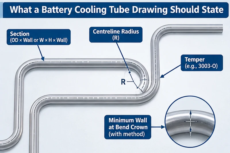
The four figures that remove most disputes are the datum straight, the angle tolerance, the ovality limit with its section, and the minimum wall at the crown.
A specification sentence that works
Three examples show the difference between a requirement and a wish.
- “Bend angle 90° ±0.5°, referenced to the datum straight marked A” is checkable
- “Ovality 6% max at the bend crown, measured across two opposing points” is checkable
- “Minimum wall 1.35 mm at the bend crown, ultrasonic, referenced to the straight” is checkable
Each sentence names a characteristic, a value and a method. A drawing built from sentences like those can be inspected by anyone with the right tool, and it can be defended in a review without the person who wrote it in the room.
Troubleshooting Inspection Disputes
When a buyer and a supplier disagree about a bent tube, the cause is almost never measurement precision. It is one of five recurring situations.
| Situation | What has usually happened | What settles it |
|---|---|---|
| Part passes at the supplier and fails at assembly | Drawing never named the plane or the datum | Agree the fixture or the datum before the next batch |
| Both parties measure angle, both are right | Different reference faces used | Write the reference face into the specification |
| Ovality rejected on a reading from the straight | Section not specified on the drawing | Re-measure at the crown and add the section to the drawing |
| Wall checked by sectioning on a production part | No non-destructive method agreed | Add ultrasonic wall to the inspection plan |
| Surface rejected after coating | Cosmetic zones never separated | Add the zone map to the drawing revision |
Four steps resolve most of them without escalation, and you can run them in an afternoon:
- Re-measure both parts to the same method, side by side
- Confirm both parties read the same drawing revision
- Check whether the disputed characteristic has a stated section or datum
- Fix the specification before fixing the part
What to Send Before an Inspection Is Agreed
Six items make an inspection plan possible, and the first is the one most often missing.
- Which characteristics are functional and which are cosmetic
- The datum straight and the bend planes, for anything with more than one bend
- The characteristic that must not fail, since that drives the method
- Whether the part carries pressure or only shape
- Whether a first article record is required, and in what format
- Volume and repeat pattern, because that decides fixture against CMM
Send those six and the inspection plan becomes a short technical document. Without them, bent tube inspection becomes a series of conversations after each rejected lot, and each conversation costs more than the plan would have. A written plan is also the only version of bent tube inspection that survives a change of inspector. Skip them and inspection becomes a series of conversations after each rejected lot.
Records deserve a retention rule rather than good intentions. Keep the first article record for the life of the part family, keep batch sampling sheets for at least the warranty period, and keep the material certificate against the lot it was consumed by. When a customer questions a batch, those three documents answer the question without re-running anything.
A request-for-quote pack that includes the inspection plan avoids most of this, and the RFQ checklist here covers the machine side of the same conversation.
How Zhuoran Fits Bent Tube Inspection
Zhuoran builds the bending machines and tooling that produce these characteristics, and a sample bend is how the numbers get proven before an order: your tube, our tooling, a part returned for angle, ovality, wall and surface measurement.
What the company will not do is accept a drawing that specifies a tolerance without a method, because that specification fails in the shop rather than in the meeting.
What good bent tube inspection looks like
Good bent tube inspection is boring, which is the point.
- The drawing names every characteristic that matters, with a method for each
- The first article is measured in full and kept as a record
- Production samples the characteristics that can drift
- Disputes get resolved by re-reading the specification rather than by re-arguing the part
A supplier that hands over a first article record with method notes is easier to trust than one that hands over a certificate with a signature. Bent tube inspection is the difference between those two documents, and the difference shows up first at assembly.
Buyers get four things wrong about bent tube inspection, and each one costs a batch.
- They buy a measuring machine before writing the specification
- They specify a tolerance without naming the section or datum
- They inspect everything at first article and almost nothing in production
- They treat a surface mark and a wall reduction as the same kind of problem
None of those is a metrology problem. All four are specification problems, and no instrument fixes a specification that was never written.
Good bent tube inspection is a short list of characteristics, a named method for each, and a record that survives a review. Everything else is optional equipment. Get the specification and the sampling plan right, and bent tube inspection stops being a source of disputes. Get them wrong, and no amount of equipment changes the outcome. That is the whole argument for writing the plan before buying the tools. Most shops learn it after one expensive rejection, and the lesson is always the same: the specification was the missing part, not the instrument. Write it first, and the tool choice becomes obvious.
Frequently Asked Questions
How is bend angle measured in production?
A checking fixture for volume work, or an angle gauge plus a plane check for lower volumes. The fixture is faster and it catches out-of-plane error, which an angle gauge alone cannot.
Where should ovality be measured?
At the crown of the bend, across two opposing points. A reading taken on the straight always passes and proves nothing about the bend.
Can wall thinning be measured without cutting the part?
Yes, with an ultrasonic thickness gauge at the crown, referenced against a reading on the straight. Sectioning remains the tool for first article and process validation.
How often should parts be sampled?
From how fast the characteristic drifts. Angle and ovality move with tooling wear, wall does not move within a proven setup, and surface is checked on every part.
Do I need a CMM for bent tube inspection?
Only when the geometry is complex enough that a fixture cannot prove it. A fixture is faster, cheaper per part and closer to how the tube is used.
What is a reasonable first article record?
Every characteristic on the drawing, measured, with the method stated and the values recorded against the drawing revision, plus the material certificate and the applied springback correction.
Reference Sources
- CRD Manufacturing, Quality Assurance for Bent Tube: Inspection & Testing Methods — source for the inspection and NDT method mapping, dimensional checks on bend angle, length and wall, and the defect categories used here. crdmfg.com
- Accurex Measurement, TUBEINSPECT — automated optical inspection of bent tubing, brake lines, hydraulic lines and wireforms against a nominal model. accurexmeasure.com
- ZEISS, Tube measurement with ZEISS INSPECT — software-driven tube measurement for inspection and reverse engineering. zeiss.com
- ASME B31.3, Process Piping — examination and acceptance framework for in-plant piping subject to code.
- ASTM A269, Standard Specification for Seamless and Welded Austenitic Stainless Steel Tubing for General Service — product tolerances on the incoming tube, which set the starting point for any wall check.
Related reading on bent tube inspection: tube bending tolerances, ovality in bent tube, wall thinning during bending, defect triage for bent tubes, springback compensation, pipe bending machine tooling.