If you’ve ever cut a tube to what looked like the right length, only to bend it and find the final piece a few millimeters short — or watched a “90°” bend spring back to 87° the moment you release the clamp — you already know why tube bending calculation matters. Getting these numbers wrong doesn’t just waste material. It eats into your production time, your tooling setup, and sometimes an entire batch. This guide walks you through tube bending calculation the way working fabricators actually use it, with real worked examples you can apply today.
What Is Tube Bending Calculation? The Core Numbers Explained
Before you touch a formula, it helps to understand what each calculation is actually solving for. Tube bending calculation comes down to four numbers that show up in almost every job, and they build on each other.
Centerline Radius (CLR): The Foundation of Every Other Calculation
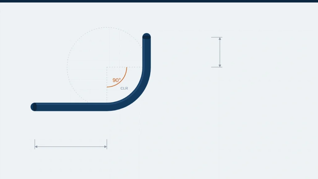
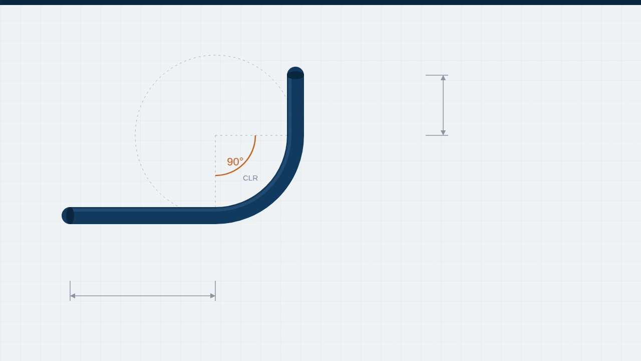
The centerline radius is the radius measured from the center of the bend to the centerline of the tube — not the inside edge, not the outside edge, but the neutral path the tube’s core follows. Every downstream calculation, from bend allowance to setback, starts from CLR.
In practice, CLR is a property of your tooling (the die), not something you calculate from scratch each time. A common shorthand is expressing CLR as a multiple of the tube’s outside diameter — a “2D bend” means CLR = 2 × OD. Tighter ratios (1.5D) increase wall thinning and ovality risk; looser ratios (3D–4D) are gentler on the material but consume more length and floor space.
Bend Allowance and Setback: How Much Material a Bend Actually Consumes
Bend allowance is the length of tube “used up” by the curve itself — the arc length along the neutral axis. If you don’t account for it, your cut-to-length calculations will always come up short, because the straight sections you measure don’t include the material consumed inside the bend.
Setback is a related but different number: the distance from the tangent point back to where two straight sections would theoretically intersect if there were no bend at all. It matters most when you’re locating a bend at a specific point along a tube.
Springback: Why Your Finished Angle Is Never Exactly Your Machine Setting
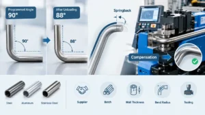
Springback is the tube’s tendency to elastically recover the instant bending force is released. It’s why a die set to bend 90° often produces a finished part closer to 86–87° in mild steel, and why harder alloys like stainless steel or 4130 chromoly spring back even more.
Wall Thinning and Ovality: The Structural Side of the Math
Every bend stretches the outer wall of the tube and compresses the inner wall — reducing wall thickness on the outside of the bend and sometimes flattening the cross-section into an oval. If you’re bending pressure-rated tubing or structural components, this calculation isn’t optional. See our deeper guide on tube wall thinning during bending.
Step-by-Step Tube Bending Calculation: Bend Allowance and Total Cut Length
This is the tube bending calculation most fabricators need most often: how long does my straight tube need to be before I bend it?
The Formula, Explained in Plain Language
- Bend Angle in radians = degrees × 0.01745
- CLR = your die’s centerline radius
- K-factor = a unitless value for where the neutral axis sits in the tube wall (commonly 0.35–0.5)
- Wall Thickness = the tube’s actual measured wall thickness
Worked Example: A 90° Bend on a 2-inch OD Tube
2-inch OD tube, 0.125-inch wall, 4-inch CLR die, 90° bend, 12 in. straight on one side, 10 in. on the other.
Step 1 — Convert the angle: 90° × 0.01745 = 1.5705 radians
Step 2 — Bend allowance (K-factor 0.447): 1.5705 × (4 + 0.447 × 0.125) = 1.5705 × 4.056 ≈ 6.37 in.
Step 3 — Total cut length: 12 + 6.37 + 10 = 28.37 in.
That 6.37 inches is material you’d completely miss if you simply added the two straight sections together — and on a tight-tolerance job, that gap is the difference between a part that fits and one that gets scrapped.
Common Unit-Conversion Mistakes That Throw Off the Whole Calculation
The single most frequent error isn’t a formula mistake — it’s a units mistake. Mixing millimeters and inches mid-calculation, forgetting to convert degrees to radians, or using nominal pipe size instead of actual measured OD will all silently produce a wrong answer that still “looks” plausible — one of the most common ways a tube bending calculation goes wrong without anyone noticing until the tube doesn’t fit.
Springback and K-Factor by Material: What the Numbers Actually Look Like
Most generic tube bending guides give you a single K-factor and move on. In practice, this part of the tube bending calculation varies meaningfully by material — and that variation is exactly what trips people up when they switch materials without adjusting their numbers.
Why Carbon Steel, Stainless Steel, Aluminum, and Copper Behave Differently
Springback is driven largely by a material’s yield strength relative to its modulus of elasticity. Materials with high yield strength relative to stiffness — like stainless steel and chromoly — spring back more than softer, more ductile materials like copper or annealed aluminum.
Typical K-Factor and Springback Ranges by Material
| Material | Typical K-Factor Range | Typical Springback (90° bend, moderate CLR) |
|---|---|---|
| Mild / carbon steel | 0.40–0.50 | 2°–5° |
| DOM steel | 0.40–0.50 | 3°–5° |
| Stainless steel (304/316) | 0.35–0.45 | 4°–7° |
| Aluminum (annealed) | 0.40–0.50 | 1°–3° |
| Copper | 0.45–0.50 | 1°–2° |
| 4130 chromoly | 0.35–0.45 | 4°–8° |
Industry reference ranges — treat as a setup starting point, not a substitute for a test bend on your actual material lot.
Overbend Compensation: The Manual Trial-and-Error Most Shops Still Use
Bend a sample to 90°, measure the actual resting angle, calculate the difference, and add that difference to your machine setting for the next bend. It works, but every new material lot, wall thickness, or CLR combination potentially requires re-characterizing springback from scratch. For a broader formula reference, see this tube bending reference sheet.
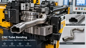
From Formula to Machine: How CNC Tube Benders Handle These Calculations
Here’s the part most tube bending calculation guides skip entirely: once you’ve worked out your bend allowance, K-factor, and springback compensation by hand, how does that translate into what the machine actually does?
Manual Calculation & Overbend
Recalculate bend allowance and springback by hand for every new material, wall thickness, or CLR. Verify with a test bend each time. Works for single jobs — becomes a bottleneck with mixed materials or multi-bend parts, and errors compound across setups.
Servo-Controlled CNC Compensation
Bend angle, rotation, and feed length are closed-loop controlled to around ±0.1°/±0.1mm. Once a springback setup is characterized for a material and wall thickness, it’s saved as a program — some systems store 200–500 — and reused instead of re-measured every time.
Why Manual Recalculation Doesn’t Scale for Multi-Bend or Multi-Material Production
Recalculating springback and bend allowance by hand works fine for a single job. It becomes a real bottleneck the moment you’re running mixed materials, multiple wall thicknesses, or parts with several bends in different planes.
How Servo-Controlled Bending Stores and Reuses Compensation Values
Many CNC systems let you input data either as direct coordinates (X, Y, Z) or as working values (Y, B, C) — bend angle, rotation angle, and feed length — so the same math you just worked through by hand maps directly onto machine parameters instead of a separate manual step. Learn more in our guide to how a CNC tube bender works.
A Complete Worked Example: Calculating a Multi-Bend Tube
Single-bend examples are useful for learning the formula, but most real parts have more than one bend — and multi-bend tube bending calculation works a little differently. Here’s how the math extends.
Laying Out Three Bends on One Tube
Three 90° bends, same 2-inch OD, 0.125-inch wall tube, 4-inch CLR die. 8 inches of straight tube between each bend, 6 inches of straight tube on each end.
Total Cut Length = 6 (end) + 6.37 (bend 1) + 8 (straight) + 6.37 (bend 2) + 8 (straight) + 6.37 (bend 3) + 6 (end)
Total Cut Length = 47.11 inches
Where Errors Typically Accumulate Across Multiple Bends
The most common mistake on multi-bend parts is marking clamp positions from the wrong reference point. Every bend’s start and end point should be measured from the tangent point — not the tube’s raw end. A small error on bend two or three compounds into a part visibly off by the final bend.
Common Tube Bending Calculation Mistakes (and How to Avoid Them)
Using the Wrong K-Factor for the Material
Applying a generic 0.5 K-factor across every material — especially when switching from mild steel to stainless or chromoly — introduces error that grows with wall thickness and tightens with CLR.
Forgetting to Account for Springback Before Cutting
Springback correction needs to happen at the machine-setting stage, not as an afterthought once the part is already out of tolerance. See our explainer on what is springback in tube bending.
Confusing Bend Allowance with Bend Deduction
Bend allowance is the length consumed by the curve itself. Bend deduction is a related but distinct concept more common in sheet metal bending — see this guide to bend allowance and bend deduction — and it’s occasionally misapplied to tube calculations.
Frequently Asked Questions
What is the formula for tube bending calculation?
The core tube bending calculation formula is Bend Allowance = Bend Angle (in radians) × (CLR + K-factor × Wall Thickness). Add the bend allowance to your straight sections to get total cut length.
How do you calculate springback in tube bending?
Bend a test piece to your target angle, measure the actual resting angle after release, and the difference is your springback value for that material and setup.
What is a good K-factor for tube bending?
Most applications use a K-factor between 0.35 and 0.5, depending on material and wall thickness.
What’s the difference between bend allowance and bend deduction?
Bend allowance is the material consumed by the bend’s arc. Bend deduction is a distinct sheet-metal-bending concept for flat pattern length.
How much material does a 90° bend consume?
A 90° bend on a 4-inch CLR die with a 2-inch OD tube consumes roughly 6.3–6.4 inches of material, using standard bend allowance formulas.
Can CNC tube benders calculate bend allowance automatically?
CNC machines don’t eliminate the need to understand these formulas, but a characterized setup can be saved and reused rather than recalculated by hand for every job.
Does wall thickness affect springback?
Yes. Thinner walls relative to CLR generally increase springback because there’s less material resisting elastic recovery.
How accurate does tube bending calculation need to be?
For most fabrication work, aim for cut lengths within a few hundredths of an inch and bend angles within a degree or two before springback correction. Tighter tolerances typically call for a verified test bend rather than formula results alone.
Tube Bending Calculation: Getting the Numbers Right, Every Time
Tube bending calculation isn’t a one-time formula you memorize and forget — it’s a set of numbers that shift with every change in material, wall thickness, and bend geometry. Getting bend allowance, springback, and cut length right the first time saves material, saves setup time, and keeps your parts within tolerance from the first piece to the last.
Still recalculating springback by hand on every material change? If repeated test-bend scrap is becoming a real cost on your production runs, our engineering team can walk through your specific tube specifications and bending requirements.