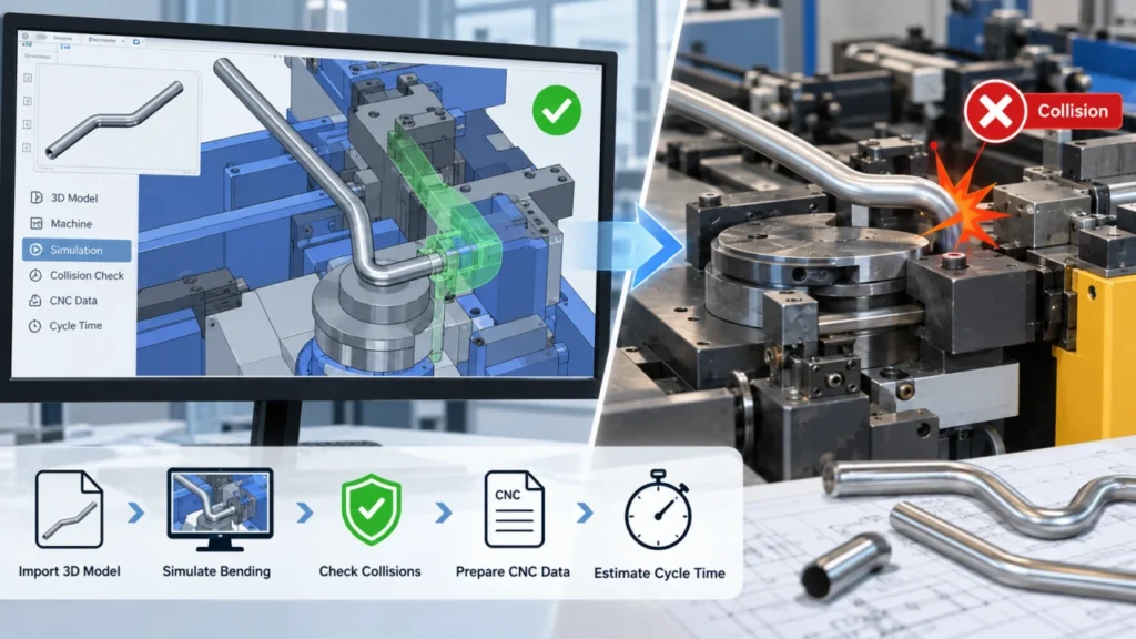
If a tube looks correct in CAD but collides with the machine during bending, the problem is discovered too late.
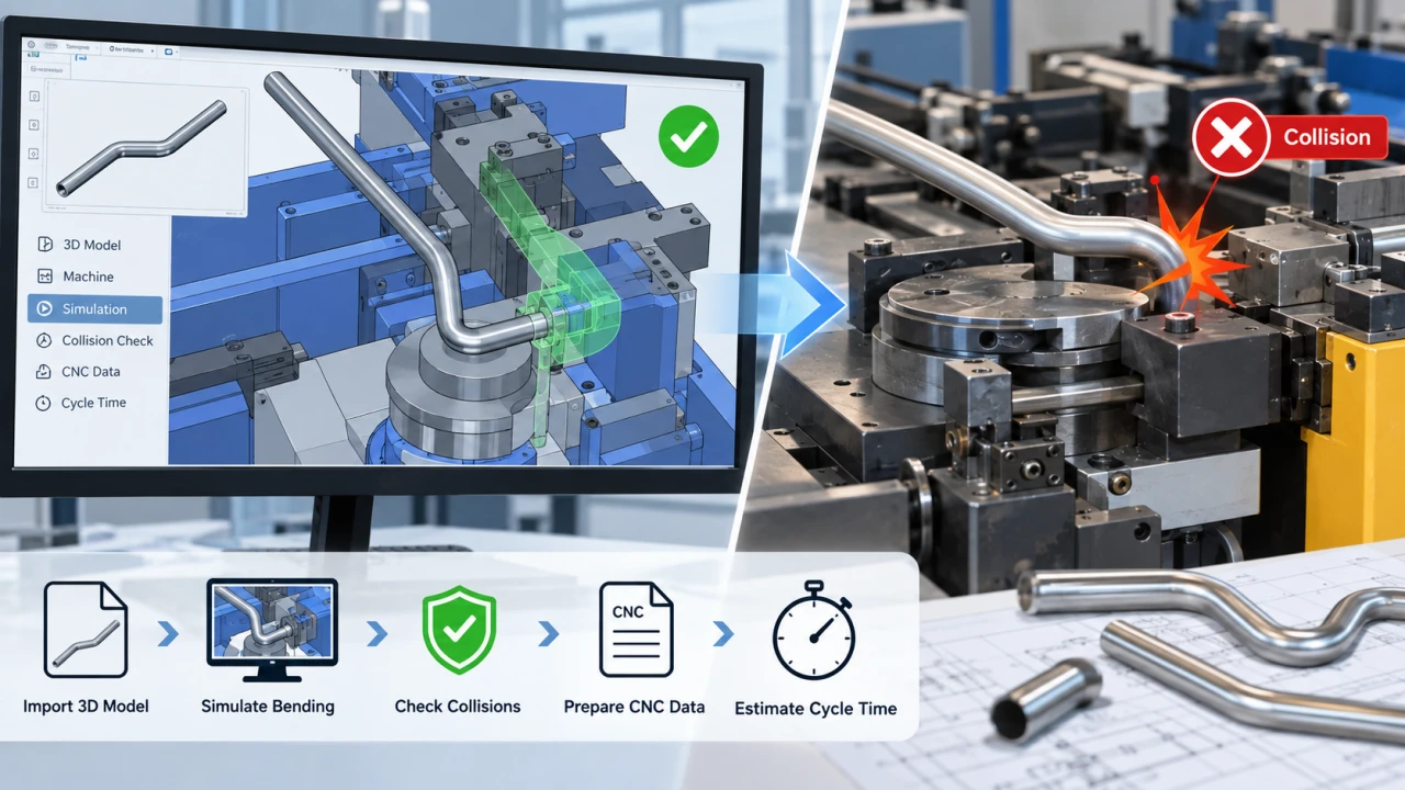
The result can be wasted material, repeated trial bending, delayed production, and difficult CNC adjustment. Tube bending simulation helps you review the bending process before production begins. You can import a 3D tube model, simulate machine movement, check for collisions, prepare CNC data, and estimate the production cycle.
However, the value of simulation depends on how closely the virtual machine matches the real one. A simulation system should not be treated as a universal software template. Each machine requires a machine-specific system modeled according to its actual type, structure, tooling position, motion axes, working range, and operating sequence.
Start with the actual machine
The simulation model should match the selected tube bending machine, its axes, tooling position, working range, and operating sequence.
Do not copy a universal model
Different machine models cannot directly use the same simulation system because their mechanical and control configurations may be different.
What Is Tube Bending Simulation?
Tube bending simulation is a digital method for reviewing how a tube will be formed inside a bending machine before the physical process starts.
The simulation can represent the 3D tube geometry, bending sequence, machine structure, bending die, clamp die, pressure die, mandrel, feeding movement, rotation movement, bending movement, and expected process time.
A simple 3D model only shows the final shape of a tube. It does not necessarily show whether the tube can be produced on a specific machine. Tube bending simulation adds machine and process conditions to the analysis.
For example, a tube may have a valid CAD shape but still create a production problem because a previous bend blocks the next movement, the tube touches the machine frame, the clamp cannot hold the tube correctly, or the required rotation exceeds the machine’s available range.
Why Machine-Specific Simulation Matters
Each tube bending machine has its own mechanical configuration. Two machines may have similar names or similar maximum tube diameters but still use different structures, axes, tooling positions, and movement limits.
A simulation system must therefore be configured for the machine it represents. The virtual machine should reflect the machine frame, axis configuration, tooling location, bending direction, control logic, and working envelope.
| Item | Generic 3D Review | Machine-Specific Simulation |
|---|---|---|
| Tube shape | Can be viewed | Can be viewed and processed |
| Machine structure | Usually not included | Modeled according to the machine type |
| Tooling position | May be missing | Configured for the actual machine |
| Axis movement | Not usually simulated | Reviewed during the bending sequence |
| Collision risk | Difficult to confirm | Checked during machine movement |
| CNC preparation | Usually outside the tool | Connected with the industrial control system |
| Cycle-time estimate | Usually unavailable | Evaluated from machine actions |
Who Uses Tube Bending Simulation?
Tube Bending Engineers
Engineers use simulation to review the bending sequence, tube orientation, feeding direction, rotation angle, tooling clearance, collision risk, and machine data before physical setup.
Production Managers
Production managers can use simulation to review preparation time, expected cycle time, equipment capacity, machine setup delays, and alternative process sequences.
Machine Buyers
Buyers can evaluate whether a machine has enough working space, suitable axes, compatible tooling, and the control functions required for the planned tube parts.
Industrial Tube Manufacturers
Typical applications include automotive exhaust tubes, HVAC tubing, industrial piping, furniture frames, hydraulic tubes, and construction equipment components.
How Does Tube Bending Simulation Work?
Match the System to the Exact Machine Model
The first step is to identify the actual bending machine. The virtual machine should reflect its mechanical structure, axis configuration, tooling arrangement, movement range, and control logic.
Import the Tube Geometry from a STEP File
A STEP file provides the three-dimensional tube geometry, including bend locations, bend angles, straight sections, spatial orientation, and end positions. The file should be checked for missing surfaces, incorrect dimensions, and unwanted geometry before simulation.
Enter Tube and Process Parameters
The process may require tube material, outside diameter, wall thickness, centerline radius, target angles, tooling configuration, mandrel condition, lubrication, feeding distance, and rotation angle.
Simulate Machine and Tube Movement
The system can simulate feeding, rotation, clamping, pressure-die movement, bending-head movement, and the sequence between multiple bends.
Check for Collisions and Interference
The system can be used to review interference between the tube, dies, clamps, mandrel, machine frame, and other moving components.
Prepare CNC Data
After the process is reviewed, the simulation system can prepare or generate CNC bending data according to the selected machine configuration and industrial control system.
Review the Estimated Cycle Time
Cycle-time simulation can estimate feeding, rotation, bending, tooling, and return movements. The final production time may also include loading, unloading, inspection, and material handling.
What Are the Benefits of Tube Bending Simulation?
Reduce Trial Bending
Without simulation, engineers may need to use physical tubes to verify the bending sequence. Simulation moves part of the review process into a virtual environment and can reduce unnecessary trial bending during early development.
Identify Machine Collisions Earlier
A complex tube may collide with the machine only after several bends have been completed. A machine-specific virtual model allows the engineer to review the movement before the machine is physically set up.
Improve Bend Sequence Planning
The order of bending can affect tube accessibility, machine clearance, tooling movement, production time, and operator convenience. Simulation helps engineers compare different sequences before production.
Connect Design Data with CNC Preparation
A STEP file belongs to the design stage, while a CNC program belongs to the production stage. An integrated simulation system helps connect the tube geometry with the data required by the selected machine.
Estimate Cycle Time Before Production
Cycle-time simulation supports production planning, capacity evaluation, quotation preparation, and equipment comparison. It should be treated as an engineering estimate rather than a guaranteed production time.
For more information about the general production workflow, see
tube bending process.
What Types of Tube Bending Processes Can Be Simulated?
Rotary Draw Bending
Rotary draw bending is widely used for accurate tube forming. The process uses tooling to control the tube while the bending die rotates it around the required radius.
Learn more about
rotary draw bending.
Multi-Axis CNC Tube Bending
CNC tube bending may use feeding, rotation, bending, and auxiliary movements. The actual axis configuration depends on the machine model, so the simulation must reflect the real equipment.
Multi-Bend Tube Components
Simulation is especially useful for tubes with multiple bends, different bend planes, short straight sections, tight clearances, complex spatial shapes, and strict orientation requirements.
What Information Is Needed for Tube Bending Simulation?
| Input | Purpose |
|---|---|
| STEP file | Defines the three-dimensional tube geometry. |
| Tube material | Affects forming behavior and springback. |
| Outside diameter | Determines machine and tooling suitability. |
| Wall thickness | Affects deformation and forming conditions. |
| Centerline radius | Defines the bending geometry. |
| Target bend angles | Establishes the production objective. |
| Machine model | Confirms the correct virtual machine system. |
| Tooling configuration | Defines the actual forming arrangement. |
| Required tolerance | Establishes the acceptance standard. |
| Production quantity | Helps evaluate cycle-time requirements. |
Simulation Versus Physical Trial Bending
Simulation can reduce uncertainty, but it cannot eliminate every production variable. The final bending result may still be affected by material batch, actual yield strength, tube wall thickness, tooling wear, lubrication, mandrel adjustment, machine condition, springback, and measurement method.
| Item | Simulation | Physical Trial Bending |
|---|---|---|
| Main purpose | Pre-production prediction and process review | Confirmation of the real forming result |
| Material usage | Usually no physical tube is consumed | Requires actual tube material |
| Collision review | Can identify risks before setup | May reveal problems after setup |
| Material springback | Cannot fully guarantee the final result | Can be measured under actual conditions |
| Final validation | Supports engineering decisions | Remains necessary for production confirmation |
If the programmed angle is 90° but the tube relaxes to 88° after unloading, the initial 2° difference can provide a starting point for springback compensation testing. It should not automatically be copied to another tube, material, batch, or machine.
For related accuracy topics, see
tube bending tolerances
and
tube deformation.
When Should You Use Tube Bending Simulation?
- Before buying a new tube bending machine.
- Before producing a complex tube part.
- When collision risk is high.
- When the tube has many bends in different planes.
- When production volume is large.
- When CNC data preparation requires greater consistency.
- When material waste during trial bending would be expensive.
How to Select a Tube Bending Simulation System
Before selecting a system, ask the supplier these questions:
- Is the simulation system matched to the exact machine model?
- Is the virtual machine modeled according to the real structure?
- Can the system import the required STEP file?
- Can it simulate feeding, rotation, and bending movements?
- Can it identify collisions and interference?
- Can it prepare CNC data for the selected controller?
- Can it estimate the bending cycle time?
- Are tooling and clamping conditions included?
- Can the supplier demonstrate the system with your own tube file?
- Is physical sample testing available after simulation?
How Zhuoran Uses an Industrial Control System for Tube Bending Simulation
Zhuoran’s tube bending simulation approach is based on the industrial control system of the CNC tube bending machine.
Each machine requires its own corresponding virtual system and 1:1 animated machine model. The machine structure, tooling position, motion axes, working range, and operating sequence must match the selected equipment.
Based on the confirmed system functions, the simulation can support 3D tube bending simulation, STEP file import, machine movement review, collision and interference simulation, CNC data preparation, cycle-time simulation, and process sequence evaluation.
Different machine models cannot directly use the same simulation system because their mechanical and control configurations may be different. The virtual result also depends on the quality of the machine model, tooling data, tube geometry, and process parameters used in the simulation.
If the machine configuration, tooling, or tube material changes, the simulation should be reviewed again.
Frequently Asked Questions
What is tube bending simulation?
Tube bending simulation is a digital process used to review tube geometry, machine movement, tooling interaction, collision risk, CNC preparation, and estimated cycle time before physical production.
Can tube bending simulation import STEP files?
A compatible simulation system can use a STEP file as the three-dimensional tube model. The file should be checked for geometry errors before simulation.
Can one simulation system work with different tube bending machines?
Not directly. Each machine requires a system configured according to its structure, tooling, axes, movement range, and control logic.
How does tube bending simulation detect collisions?
The system simulates the movement of the virtual tube, tooling, and machine components and identifies possible interference during the bending sequence.
Can tube bending simulation generate CNC data?
A machine-integrated simulation system can prepare or generate CNC bending data according to the selected machine configuration and controller.
Can simulation calculate the exact production cycle time?
Simulation can estimate machine movement time. The final production cycle may also include loading, unloading, inspection, material handling, and operator actions.
Does tube bending simulation replace physical trial bending?
No. Simulation reduces process uncertainty, but physical trial bending is still needed to confirm the final result under actual material, tooling, and machine conditions.
What information is needed for a simulation evaluation?
Useful information includes the STEP file, tube material, outside diameter, wall thickness, bend radius, target angles, tolerance, tooling information, machine model, and bending sequence.
Need a Machine-Specific Tube Bending Simulation?
Send your STEP file, machine model, tube material, outside diameter, wall thickness,
centerline radius, target bend sequence, and tolerance requirements for an engineering review.
Conclusion
Tube bending simulation helps engineers review the bending process before using production material. It can support STEP file import, 3D machine animation, collision checking, CNC data preparation, and cycle-time evaluation.
The most important point is that the simulation system must match the real machine. Each machine model requires a corresponding 1:1 virtual representation. Different machines cannot directly share the same simulation system because their structures, tooling positions, motion axes, working ranges, and control sequences may differ.
When the simulation is connected with the industrial control system, it provides a practical link between tube design and CNC production. It helps engineers identify process risks earlier and gives buyers more information when evaluating a machine.
Simulation does not remove the need for physical validation. The final result still depends on the actual tube material, batch, wall thickness, tooling, lubrication, machine condition, and springback behavior.
If you want to evaluate a tube bending process, prepare your STEP file, machine model, tube material, outside diameter, wall thickness, centerline radius, target angles, tolerance, and required bending sequence.