When you design a bent tube, the straight dimensions on your drawing do not tell you the complete cut length. Part of the tube becomes the bend itself. Bend allowance helps you calculate how much tube length is used through that bend.
Getting this value wrong can shift your final endpoints, increase trimming, and make multi-bend parts harder to control. This guide explains bend allowance for tube processing, the basic formula, a calculation example, and the practical factors you need to check before using the result in production.
Quick Answer: What Is Bend Allowance?
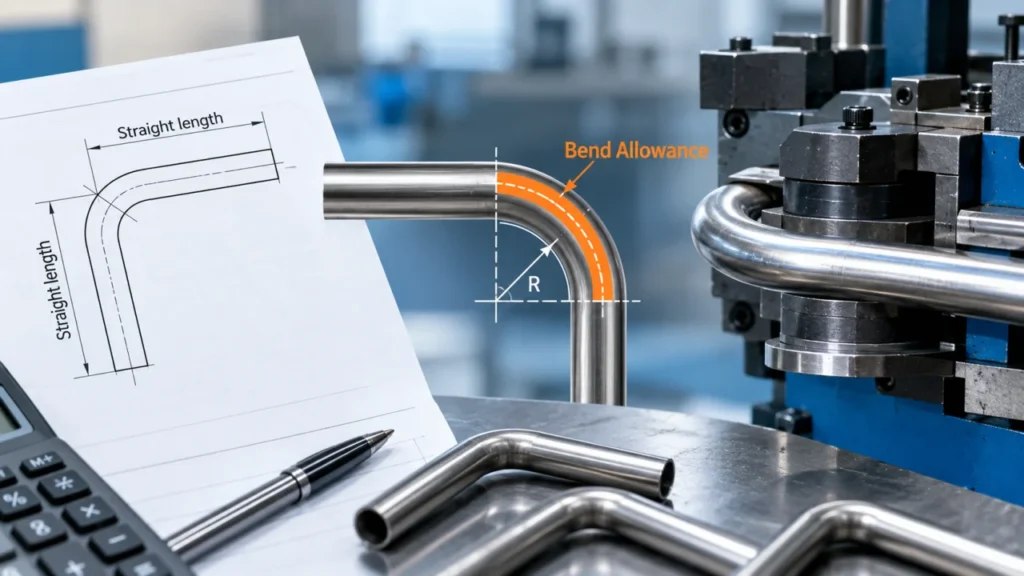
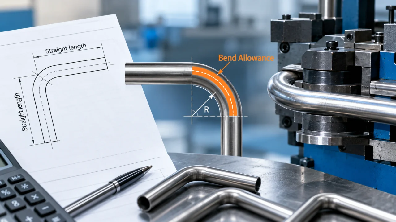
Bend allowance is the length of material that forms the curved section of a bend. In practical tube bending, it is commonly calculated as the arc length along the tube’s centerline.
For a constant-radius bend:
BA = (π × CLR × A) / 180
where BA is bend allowance, CLR is center line radius, and A is bend angle in degrees. This gives you the theoretical tube length consumed by the bend.
What Is Bend Allowance in Tube Processing?
Imagine a straight tube marked at two tangent points. After bending, the section between those points becomes an arc. The length of that arc is the bend allowance.
It matters because the finished part consists of more than its straight sections:
Developed Tube Length = Straight Sections + Bend Sections
For a part with several bends, you repeat the calculation for each bend and combine those arc lengths with the required straight lengths. This sounds simple, but one distinction matters.
Tube Bend Allowance Is Not Exactly the Same as Sheet Metal Bend Allowance
If you search for bend allowance online, you will often see:
BA = (π / 180) × A × (R + K × T)
This formula uses an inside radius, material thickness, and K-factor to locate the neutral axis. It is widely used for sheet-metal flat-pattern development.
Tube bending is commonly handled differently. A tube drawing and tube bender normally work around a center line radius (CLR). If your bend radius is already specified at the tube centerline, the practical arc calculation becomes:
BA = (π / 180) × A × CLR
You should therefore confirm where the radius is measured before choosing a formula. Mixing inside radius and center line radius is an easy way to introduce an error before the machine even starts. See TestTalkHQ’s guide to CLR and bend deduction for a detailed breakdown.
The Basic Tube Bend Allowance Formula
For a constant-radius circular bend:
BA = π × CLR × A / 180
| Symbol | Meaning | Unit |
|---|---|---|
| BA | Bend allowance | mm or inch |
| CLR | Center Line Radius | mm or inch |
| A | Bend angle | degrees |
| π | Pi | ≈ 3.14159 |
The formula is simply the arc-length equation for a circle. A complete circle contains 360°, so the full circumference is 2πR. A 90° bend uses one-quarter of the circumference, and a 180° bend uses half. The formula converts this relationship into the length of tube contained in your bend.
Bend Allowance Calculation Example
Suppose your drawing specifies:
- Tube OD: 50 mm
- Wall thickness: 2 mm
- CLR: 100 mm
- Bend angle: 90°
For the basic centerline calculation: BA = π × 100 × 90 / 180, therefore BA ≈ 157.08 mm. About 157.1 mm of centerline length is contained in the 90° bend.
Notice that OD and wall thickness were not needed to calculate this geometric centerline arc. That does not mean they are unimportant to the bending process. They strongly affect tooling selection, deformation, wall thinning, ovality, springback, and whether the requested CLR is practical. They simply answer a different engineering question.
Quick Bend Allowance Reference
For a fixed CLR, bend allowance changes directly with bend angle. Using a 100 mm CLR:
| Bend Angle | Bend Allowance |
|---|---|
| 30° | 52.36 mm |
| 45° | 78.54 mm |
| 60° | 104.72 mm |
| 90° | 157.08 mm |
| 120° | 209.44 mm |
| 180° | 314.16 mm |
These values are geometric examples, not production compensation values. If you double the CLR while keeping the same angle, you also double the arc length.
CLR Is the First Number You Need to Check
Center Line Radius is the distance from the center of the bend to the centerline of the tube. It should not be confused with inside bend radius, outside bend radius, tube OD, or bend diameter.
For a round tube, if you know the inside bend radius and tube outside diameter, the geometric relationship is:
CLR = Inside Radius + OD / 2
For example, with an inside radius of 75 mm and a tube OD of 50 mm, CLR = 75 + 25 = 100 mm. You can now use 100 mm in the centerline bend allowance formula.
Before calculating a production blank, always check the radius convention on the drawing. A value marked simply as “R100” can be ambiguous if the drawing does not show where that radius is measured.
Bend Allowance vs. Bend Deduction vs. Setback
These terms are related, but they should not be used interchangeably.
Bend Allowance
Bend allowance describes the length contained in the curved portion of the part. For tube work using CLR: BA = CLR × θ, when θ is expressed in radians.
Setback
Setback describes the geometric distance between a tangent point and the theoretical intersection of the straight tube centerlines. For a simple bend: Setback = CLR × tan(A / 2). A 90° bend with a 100 mm CLR therefore has a theoretical setback of 100 × tan(45°) = 100 mm.
Bend Deduction
Bend deduction is especially common in flat-pattern and sheet-metal calculations. If your tube drawing is based on tangent-to-tangent centerline dimensions, directly working with straight lengths and centerline bend arcs is often clearer than importing sheet-metal bend-deduction conventions.
The important rule is simple: know how your drawing dimensions are defined before calculating the cut length.
How to Calculate the Developed Length of a Bent Tube
For a simple part with one bend, the developed length is: L = L₁ + BA + L₂, where L₁ and L₂ are straight centerline lengths measured to the bend tangent points.
For a multi-bend tube: L = Σ Straight Lengths + Σ Bend Allowances.
This approach works well when your drawing already provides tangent-point geometry. If the drawing instead provides outside envelope dimensions or theoretical intersections, you first need to convert those into the correct straight tangent lengths. That distinction is one of the main reasons two people can use the same bend allowance formula and still calculate different blank lengths.
What Actually Affects Bend Allowance Accuracy?
The formula gives you geometry. Production adds another layer. Several factors determine whether the calculated value leads to the final part you expect.
1. Bend Radius Definition
First verify whether the drawing uses inside radius, center line radius, or outside radius. Do not enter an inside radius directly into a formula that expects CLR.
2. Bend Angle
Bend allowance increases directly with bend angle. Even a small angle difference changes the arc length, and errors can accumulate on multi-bend parts.
3. Springback
After the bending force is removed, elastic recovery can cause the tube to open slightly. The machine may need to bend beyond the nominal drawing angle to reach the required final angle. Springback depends on material, tube geometry, bend radius, tooling, and process conditions, so it should be established through validated bending data or trial bends.
4. Tube OD and Wall Thickness
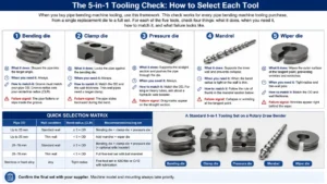
OD and wall thickness may not appear in the basic CLR arc formula, but they are critical to process feasibility. A large OD-to-wall-thickness ratio makes the tube more sensitive to distortion. For demanding bends, a mandrel and wiper die may be required to control wrinkling, flattening, ovality, and wall thinning. This is where geometric calculation and actual tube-bending engineering begin to separate.
5. Tooling and Actual Formed Radius
Your calculation assumes the tube follows the intended bend geometry. In production, the bend die, pressure die, clamp die, mandrel position, material behavior, and machine settings influence the formed part. For repeat production, use measured parts to verify the relationship between theoretical geometry and actual machine output.
Why Bend Allowance Becomes More Important on Multi-Bend Parts
A single 90° bend is easy to understand; a tube containing six or eight bends is different. You now have a sequence of straight → bend → straight → rotation → bend, where an error near the beginning can shift later bend positions and move the final endpoint.
For CNC tube bending, you need more than a total cut length—you need a complete definition of the part geometry. Typical inputs include tube OD, wall thickness, material, bend angle, CLR, distance between bends, bend plane/rotation, and final endpoint requirements. See BenderParts’ guide to calculating tube bends for related geometry.
Bend Allowance and YBC Tube Bending Data
For CNC tube bending, part geometry is often represented through YBC data. The concept normally describes three actions:
- Y — Feed: how far the tube advances between bends.
- B — Rotation: how far the tube rotates around its axis.
- C — Bend: the required bend angle.
Bend allowance helps you understand the material consumed by the curved geometry, while YBC data tells the machine how to produce the sequence. These are related, but not the same thing. You should not treat bend allowance as a replacement for complete CNC bending data.
A Better Workflow for Production Parts
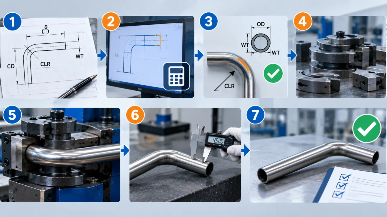
For a new tube, use the formula as the starting point rather than the final process specification. A practical workflow is:
- Confirm the drawing convention. Identify OD, wall thickness, material, CLR, bend angles, tangent points, and final dimensions.
- Calculate the theoretical geometry. Determine each bend arc and the required straight lengths.
- Check bend feasibility. Review CLR-to-OD ratio, wall thickness, material, bend spacing, and tooling requirements.
- Select the tooling and machine setup. Match the bend die and supporting tooling to the tube and geometry.
- Run a sample bend. Use actual material from the intended production condition when possible.
- Measure the finished part. Check bend angle, radius, endpoint position, ovality, wall condition, and critical dimensions.
- Correct and save the production data. Apply validated compensation rather than repeatedly changing the theoretical drawing.
This separates geometry from process compensation, which makes troubleshooting much easier.
Common Bend Allowance Mistakes
Using Inside Radius as CLR
If the formula requires CLR but you enter the inside radius, the calculated arc becomes too short. Convert the radius first.
Copying a Sheet Metal K-Factor Formula Without Checking the Application
K-factor is useful for locating a neutral axis in sheet-metal flat-pattern calculations. But if your tube drawing already specifies CLR, adding another K-factor correction can mix two different conventions.
Ignoring Tangent Points
Bend allowance only tells you the arc length. You still need to know where the bend starts and ends, especially when the drawing gives overall dimensions instead of tangent-to-tangent dimensions.
Treating the Formula as a Machine Setting
A calculated 90° bend does not automatically mean that commanding exactly 90° will produce a measured 90° finished bend. Material springback and machine/tooling conditions still matter.
Skipping the Trial Bend
For loose fabrication work, theoretical geometry may be sufficient. For a repeat production part with controlled endpoints or tight tolerances, a sample bend provides the data you need to validate the program. Our sample service supports this validation step.
How CNC Tube Bending Improves Repeatability
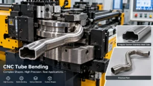
Once your geometry and process corrections are established, CNC control reduces the operator-dependent positioning required between bends. Feeding, rotation, and bending are controlled as a programmed sequence, which is especially useful for parts with several bends in different planes.
Zhuoran Machinery’s CNC tube bending range includes 2-axis through 6-axis configurations, with different machine sizes and tooling arrangements for different tube-processing requirements. For complex production parts, review the CNC pipe bending machine range to match the machine configuration to your tube geometry rather than selecting a bender from bend allowance alone.
Bend Allowance FAQ
Is bend allowance the same as bend radius?
No. Bend radius describes the radius of the curve; bend allowance describes the length of material contained in that curve. You need both the bend radius and bend angle to calculate the theoretical arc length.
How do you calculate bend allowance for a 90-degree tube bend?
If you know the center line radius: BA = π × CLR × 90 / 180, which simplifies to BA = π × CLR / 2. For a 100 mm CLR, the theoretical bend allowance is approximately 157.08 mm.
Does tube diameter affect bend allowance?
Not directly when you calculate the arc from an already specified center line radius. However, tube OD affects the relationship between inside radius and CLR and strongly affects bend feasibility, tooling requirements, ovality, and wall deformation.
Does wall thickness affect tube bend allowance?
If your calculation uses a specified CLR, wall thickness is not part of the basic centerline arc formula. If you are deriving a neutral-axis radius from an inside radius, wall thickness becomes relevant. Wall thickness is also critical when evaluating whether the tube can be bent without unacceptable deformation.
Is bend allowance the same as bend deduction?
No. Bend allowance represents material length through the bend. Bend deduction is a different layout value commonly used to determine developed blank length from finished dimensions. Do not switch between the two without checking the dimensioning method.
What is CLR in tube bending?
CLR means Center Line Radius. It is measured from the center of the bend to the centerline of the tube. It is one of the most important geometric inputs for tube bend calculations and tooling selection.
Do I need a K-factor for tube bending?
Not necessarily. If your tube geometry is defined directly by center line radius, you can calculate the theoretical bend arc from CLR and bend angle. K-factor becomes relevant when you need to estimate the neutral-axis position from another radius convention, and it is much more prominent in sheet-metal calculations.
Why is my finished tube different from the calculated geometry?
The calculation describes theoretical geometry. Your finished part can also be affected by springback, material variation, actual tooling geometry, machine setup, mandrel position, pressure-die settings, tube deformation, and measurement method. Validate critical parts with sample bends and measured production data. You can also review our general FAQ for more guidance.
Final Thoughts
Bend allowance gives you the geometric starting point for determining how much tube is contained in each bend. For production work, combine the formula with the correct CLR, tangent geometry, tooling selection, material behavior, and verified machine compensation.
If you are evaluating a new bent-tube part, send your drawing or STEP file, material, tube OD, wall thickness, CLR, bend angles, quantity, and required tolerances. These inputs make it possible to evaluate both the calculation and the actual bending process.