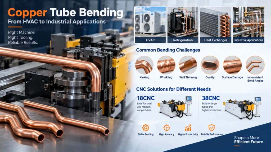
Copper tube bending is widely used in HVAC, refrigeration, heat exchanger, and industrial tube-processing applications. Copper is relatively ductile and can be formed into complex shapes, but this does not mean every copper tube can be bent with the same machine, tooling, or process settings.
During production, you may face kinking, wrinkling, wall thinning, ovality, surface damage, or inconsistent bend angles. These problems are usually related to the relationship between tube diameter, wall thickness, material condition, bending radius, tooling, and machine control.
This guide explains the main challenges of copper tube bending, how to select the right CNC machine, and how 18CNC and 38CNC machines can support different copper tube processing requirements.
What Is Copper Tube Bending?
Copper tube bending is the process of forming a straight copper tube into a required angle or three-dimensional shape without cutting and joining separate sections.
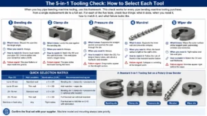
The tube is positioned and supported by a combination of bending tools. Depending on the application, the tooling may include:
- Bend die
- Clamp die
- Pressure die
- Mandrel
- Wiper die
The correct combination depends on the tube diameter, wall thickness, centerline radius, bend angle, material condition, and required surface quality.
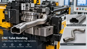
Copper tube bending can be performed manually for installation and maintenance work. However, CNC tube bending is more suitable when production requires repeatability, controlled positioning, automatic feeding, or complex tube geometries.
For more information about the general process, see our guide to the tube bending process.
Why Is Copper Suitable for Tube Bending?
Copper has good ductility and is commonly used in applications where tubes must be formed into compact and reliable flow paths.
Copper tube forming characteristics are also discussed in the
Copper Tube Handbook
published by the Copper Development Association.
Typical applications include:
- Air-conditioning systems
- Refrigeration equipment
- Heat exchangers
- Condensers
- Evaporators
- Copper tube assemblies
- Industrial cooling systems
However, copper tubes are available in different sizes, wall thicknesses, and material conditions. These differences affect the force required for bending and the risk of deformation.
A copper tube that bends successfully in one application may require different tooling or speed settings in another application.
Common Challenges in Copper Tube Bending
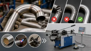
Kinking and Local Collapse
Kinking occurs when the tube loses its shape during bending. The tube may fold sharply on the inside of the bend or collapse near the bending point.
This problem is more likely when:
- The bending radius is too small.
- The wall thickness is not sufficient for the application.
- The tube is not properly supported.
- The tooling does not match the tube size.
- The bending speed is not correctly adjusted.
A mandrel can support the inside of the tube during bending. This helps maintain the tube cross-section and reduce local collapse.
Wrinkling on the Inside of the Bend
The inside of a bend is compressed during the forming process. If the material cannot flow smoothly, wrinkles may appear.
Wrinkling can be influenced by:
- Tube wall thickness
- Material condition
- Bend radius
- Pressure die position
- Wiper die configuration
- Lubrication
- Bending speed
For demanding applications, the wiper die and pressure die must be selected according to the actual tube and bend geometry. A standard tool configuration should not automatically be applied to every copper tube.
Wall Thinning and Ovality
The outside of the bend is stretched while the inside is compressed. As a result, the wall thickness may change locally and the tube cross-section may become oval.
Wall thinning and ovality may affect:
- Flow performance
- Connection quality
- Pressure resistance
- Appearance
- Assembly accuracy
- Final product tolerance
If the tube is used in HVAC or refrigeration equipment, these changes should be considered during both machine selection and quality inspection.
You can also review our technical pages about tube wall thinning and tube ovality.
Cracking and Surface Damage
Copper is ductile, but cracking can still occur when the forming conditions are unsuitable.
Possible causes include:
- Excessive deformation
- Inappropriate bending radius
- Material condition
- Tooling mismatch
- Poor lubrication
- Damaged tooling surfaces
- Excessive bending speed
Surface damage may appear as scratches, marks, or pressed areas. These problems are especially important when the tube remains visible in the final assembly or must be connected to other components.
Inconsistent Bend Angles
A small angle variation can create assembly problems when several tubes must fit into a fixed HVAC or heat exchanger structure.
Inconsistent bend angles may result from:
- Manual positioning errors
- Inconsistent feeding
- Incorrect tool alignment
- Variation in material condition
- Unstable process settings
- Inadequate machine control
CNC equipment can improve repeatability by controlling feeding, rotation, and bending movements. The specified feeding, rotation, and bending precision of the applicable machines is ±0.1.
Key Parameters for Copper Tube Bending
Tube Outside Diameter
Tube outside diameter is one of the first parameters to confirm when selecting a machine.
The commonly used copper tube bending models from Zhuoran include:
- 18CNC: maximum tube diameter of 18 mm
- 38CNC: maximum tube diameter of 38 mm
The machine should be selected according to the actual tube diameter, tooling requirements, bend geometry, and production conditions.
A machine should not be selected only because its maximum diameter appears larger than the tube. The tooling and required bending radius must also be evaluated.
Wall Thickness
The maximum wall thickness for the applicable copper tube bending configuration is 2 mm.
Wall thickness affects:
- Bending force
- Resistance to collapse
- Wall thinning
- Wrinkle formation
- Required tooling support
- Final dimensional stability
Two tubes with the same outside diameter may require different process settings if their wall thicknesses are different.
Minimum Bending Radius
The minimum bending radius is 1.5D, where D represents the tube diameter.
For example, if the tube diameter is 10 mm, a 1.5D bending radius corresponds to a 15 mm radius.
The actual result still depends on the tube material, wall thickness, tooling, bend angle, and product geometry. The 1.5D value should therefore be used as a machine and process reference, not as a reason to ignore the complete tube specification.
Bending Speed and Control
The bending speed can be adjusted through the control system.
This is important because different copper tube applications may require different settings. A thin-wall tube, a larger tube, or a tight-radius bend may require a different speed from a simple bend with a larger radius.
Adjustable speed helps the operator or process engineer balance:
- Forming stability
- Surface quality
- Cycle requirements
- Material response
- Defect prevention
A fixed speed should not be assumed to be suitable for every copper tube.
Accuracy
The specified feeding, rotation, and bending precision is ±0.1.
This helps control the position and angle of the tube during processing. The final product tolerance should still be confirmed against the customer drawing, material condition, tooling configuration, and inspection method.
18CNC vs. 38CNC for Copper Tube Bending
| Feature | 18CNC | 38CNC |
|---|---|---|
| Maximum tube diameter | 18 mm | 38 mm |
| Maximum wall thickness | 2 mm | 2 mm |
| Minimum bending radius | 1.5D | 1.5D |
| Bending speed | Adjustable through the control system | Adjustable through the control system |
| Feeding precision | ±0.1 | ±0.1 |
| Rotation precision | ±0.1 | ±0.1 |
| Bending precision | ±0.1 | ±0.1 |
| Automatic feeding | Supported | Supported |
| Automatic cutting | Custom configuration required | Custom configuration required |
| Automatic unloading | Custom configuration required | Custom configuration required |
| Mandrel support | Supported | Supported |
| Wiper die support | Supported | Supported |
| Pressure die support | Supported | Supported |
When Should You Choose 18CNC?
The 18CNC machine is suitable when the copper tube diameter does not exceed 18 mm.
It may be considered for:
- Small and medium copper tubes
- HVAC tube assemblies
- Refrigeration components
- Heat exchanger tubing
- Compact production layouts
- Applications requiring automatic feeding
The final machine configuration should still be confirmed using the tube drawing and tooling requirements.
When Should You Choose 38CNC?
The 38CNC machine supports copper tube diameters up to 38 mm.
It may be more suitable when:
- The tube diameter is greater than 18 mm.
- The product requires larger bending tools.
- The tube wall thickness is up to 2 mm.
- The part contains larger bends or more demanding geometry.
- The production line requires a larger machine platform.
The 38CNC should not be treated as a universal solution for every copper tube. The final selection depends on the complete tube specification.
Tooling for Copper Tube Bending
Mandrel
A mandrel supports the inside of the tube during bending.
It can help reduce:
- Local collapse
- Excessive ovality
- Inside-wall deformation
- Loss of tube cross-section
Mandrel selection should be based on the tube diameter, wall thickness, bend radius, and required shape quality.
Wiper Die
A wiper die helps control material movement on the inside of the bend.
It can be useful when the tube is thin-walled or when the bend radius is relatively tight. Incorrect positioning or unsuitable tooling may increase the risk of wrinkling.
Pressure Die
A pressure die provides additional support during the bending process.
It helps control the tube as it moves around the bend die. The pressure die must be matched to the tube size and the required bending geometry.
Additional guidance on copper tube bending tools, lubrication, and forming support is available in the
Kembla Plumbers Handbook.
Clamp Die and Bend Die
The clamp die holds the tube securely. The bend die defines the forming path and centerline radius.
Both tools must match the tube and the product drawing. Tooling designed for one diameter or radius should not automatically be transferred to another application.
More information is available in our guide to tube bending tooling.
How to Prevent Defects During Copper Tube Bending
Match the Machine to the Tube Diameter
Select the machine according to the maximum tube diameter:
- Up to 18 mm: consider the 18CNC.
- Up to 38 mm: consider the 38CNC.
Also confirm the wall thickness, radius, tooling, and product geometry before making a final decision.
Use the Correct 1.5D Bending Radius
The minimum bending radius is 1.5D.
If the required product radius is smaller than the recommended machine and tooling range, the risk of wrinkling, ovality, and local collapse may increase.
Use Proper Tooling Support
The 18CNC and 38CNC machines support:
- Mandrels
- Wiper dies
- Pressure dies
The correct configuration depends on the tube and the product drawing. Tooling should be reviewed before production begins.
Adjust the Bending Speed
Because bending speed can be adjusted through the control system, the process can be adapted to different tube conditions.
The speed should be selected according to tube diameter, wall thickness, bend radius, material condition, required surface quality, and production requirements.
Inspect the Finished Tube
Quality inspection should include:
- Bend angle
- Tube diameter
- Surface condition
- Wrinkles
- Kinks
- Cracks
- Ovality
- Connection position
- Overall dimensions
A machine trial or sample evaluation can help confirm whether the selected machine and tooling are suitable.
Automation Options for Copper Tube Bending
Automatic Feeding
Both 18CNC and 38CNC support automatic feeding.
Automatic feeding can help reduce manual positioning errors and improve production consistency. It is particularly useful when the same tube geometry must be produced repeatedly.
Automatic Cutting
Automatic cutting is available through customized configuration.
It should not be assumed to be a standard function of every machine. The cutting method depends on the product, tube length, line layout, and production requirements.
Automatic Unloading
Automatic unloading also requires customization.
The unloading method may be designed according to:
- Tube shape
- Finished part length
- Production layout
- Collection method
- Downstream process
Customized Production Lines
For customers requiring a more complete production solution, automatic feeding, cutting, and unloading can be evaluated as part of a customized line.
The correct configuration should be determined after reviewing:
- Tube drawing
- Process sequence
- Required output
- Available floor space
- Operator workflow
- Inspection requirements
Copper Tube Bending for HVAC, Refrigeration, and Heat Exchangers
Copper tube bending is commonly used in HVAC, refrigeration, and heat exchanger production.
Zhuoran has application experience in these areas. However, each product still requires a separate evaluation because tube geometry, bend radius, wall thickness, and connection locations may be different.
HVAC Applications
HVAC products often require compact tube paths and repeatable bend positions. A suitable CNC machine can help improve feeding, rotation, and bending consistency.
Refrigeration Applications
Refrigeration components may require accurate tube routing and reliable connections. Surface damage, incorrect bend angles, and ovality can affect later assembly.
Heat Exchanger Applications
Heat exchanger tubes often contain multiple bends and fixed connection positions. Machine selection should consider the complete three-dimensional geometry rather than a single bend.
Why Application-Specific Tooling Matters
Different products may use different:
- Tube diameters
- Wall thicknesses
- Bend angles
- Centerline radii
- Tooling combinations
- Loading and unloading methods
This is why the machine and tooling should be evaluated from the actual drawing.
How to Select a Copper Tube Bending Machine
Use the following process before selecting equipment:
- Confirm the tube outside diameter.
- Confirm the wall thickness.
- Confirm the copper material and condition.
- Confirm the minimum bending radius.
- Confirm the bend angle and tube geometry.
- Select between 18CNC and 38CNC.
- Review mandrel, wiper die, and pressure die requirements.
- Confirm automatic feeding requirements.
- Confirm whether cutting or unloading must be customized.
- Review the expected production process.
Information to Send Before Machine Evaluation
To evaluate a copper tube bending solution, prepare:
- Tube outside diameter
- Wall thickness
- Copper material
- Material condition
- Bend radius
- Bend angle
- Tube drawing
- Target production volume
- Required accuracy
- Automatic feeding requirements
- Cutting requirements
- Unloading requirements
This information helps the engineering team evaluate the machine model, tooling configuration, and automation requirements more accurately.
Frequently Asked Questions About Copper Tube Bending
What is the maximum tube diameter for the 18CNC machine?
The 18CNC machine can process copper tubes with a maximum diameter of 18 mm. The final application should still be reviewed according to the wall thickness, bending radius, tube geometry, and tooling requirements.
What is the maximum tube diameter for the 38CNC machine?
The 38CNC machine can process copper tubes with a maximum diameter of 38 mm. It is designed for applications requiring a larger tube-processing range than the 18CNC.
Can these machines bend copper tubes with a wall thickness of 2 mm?
The applicable copper tube bending configuration supports a maximum wall thickness of 2 mm. The final result depends on the tube diameter, material condition, bending radius, tooling, and product geometry.
What is the minimum bending radius?
The minimum bending radius is 1.5D, where D represents the tube diameter. The actual production result should be confirmed using the specific tube and tooling configuration.
Can the bending speed be adjusted?
Yes. The bending speed can be adjusted through the control system. This allows the process to be adapted to different tube sizes, wall thicknesses, bending radii, and production requirements.
Do the machines support automatic feeding?
Yes. Both 18CNC and 38CNC support automatic feeding. This can help reduce manual positioning work and improve production consistency.
Can automatic cutting and unloading be added?
Yes. Automatic cutting and unloading can be provided through customized configurations. These functions should be evaluated according to the tube shape, process sequence, production layout, and customer requirements.
Do the machines support mandrels, wiper dies, and pressure dies?
Yes. The machines support mandrels, wiper dies, and pressure dies. The correct tooling combination should be selected according to the tube diameter, wall thickness, bend radius, and product drawing.
Conclusion
Successful copper tube bending requires more than selecting a machine by tube diameter.
You should evaluate the complete relationship between tube diameter, wall thickness, bending radius, material condition, tooling, machine control, accuracy, and automation.
The 18CNC supports copper tube diameters up to 18 mm, while the 38CNC supports diameters up to 38 mm. The applicable maximum wall thickness is 2 mm, and the minimum bending radius is 1.5D.
Both machines support adjustable bending speed, automatic feeding, and mandrel, wiper die, and pressure die configurations. Automatic cutting and unloading can be customized according to the production line requirements.
If you are evaluating a copper tube bending solution, send your tube drawing, diameter, wall thickness, bending radius, bend angle, and automation requirements. The engineering team can then help assess the suitable machine model and tooling configuration.