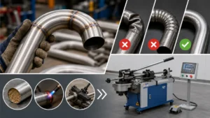
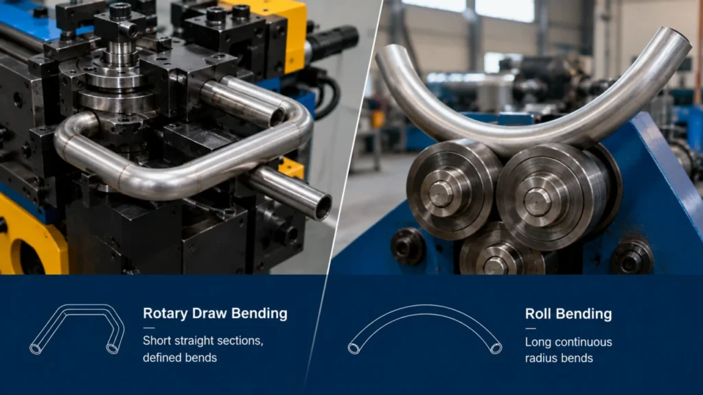
Two machines may accept the same tube diameter yet produce very different parts. A frame support with short straight sections and defined bends presents a different job from a long architectural arc. When comparing rotary draw vs roll bending, start with the finished geometry, then check tooling, tolerances, handling, and production requirements. Choose a process and tooling package that can meet your drawing and production requirements at an acceptable total cost.
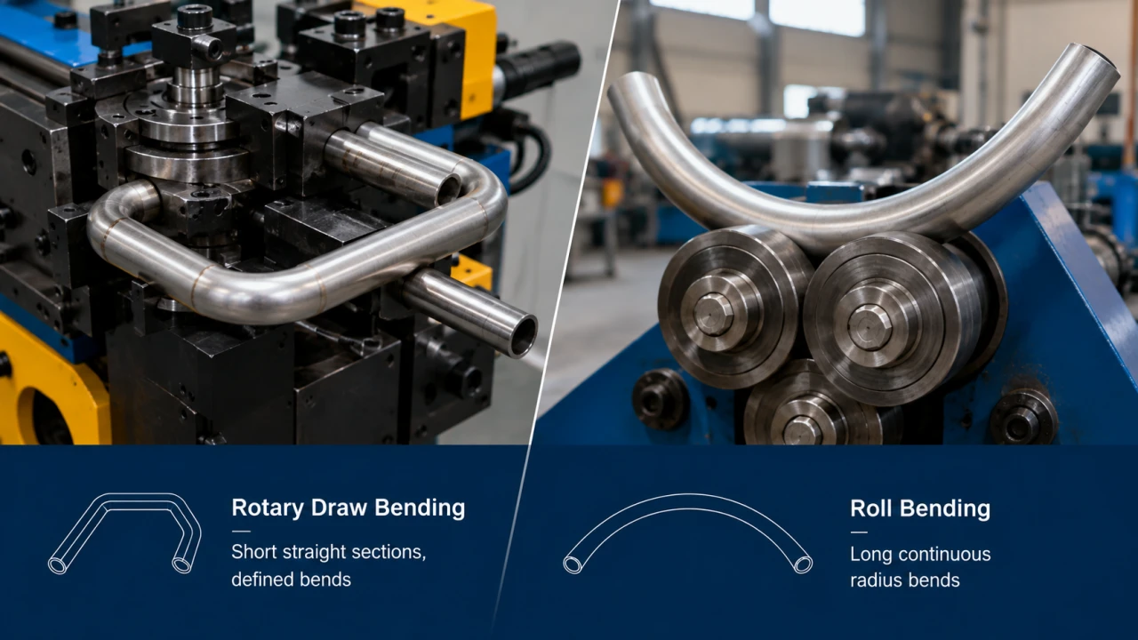
Rotary Draw vs Roll Bending: The Main Difference
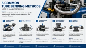
Rotary draw bending pulls a clamped tube around a bend die. Roll bending progressively curves a tube as it passes through positioned rollers. That difference affects how you establish the radius, support the tube, and manage the ends.
Rotary Draw Bending: Forming Around a Bend Die
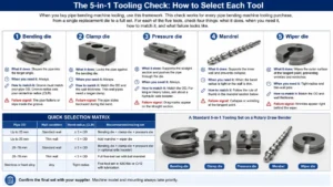
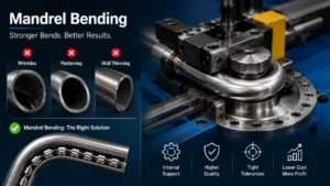
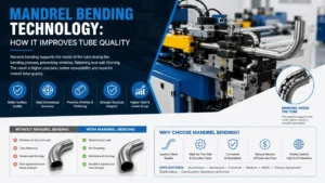
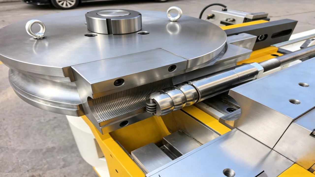
The clamp holds the tube against a rotating bend die, while a pressure die supports the straight section entering the bend. The bend die establishes the nominal centerline radius. For demanding bends, a mandrel supports the tube internally, while a wiper die helps control wrinkling near the bend tangent. Bend Tooling explains this tooling arrangement.
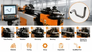
This process suits components with defined bends separated by straight lengths. On suitably configured CNC equipment, you position successive bends through programmed feeding and tube rotation. Tool access and clearance still determine whether the complete part can be made in one setup.
Roll Bending: Forming Through Rollers
Roll bending uses roller positions and tube travel to establish curvature. A basic arrangement uses three rollers, although other configurations exist. Parts may require several passes to reach the intended profile. Typical shapes include broad arcs and rings; suitable equipment can also produce helical shapes. The SME tube-bending study guide describes the underlying methods.
Changing curvature does not necessarily require a new roller set. However, the available radius range depends on the machine, section, material, and tooling.
Key Differences at a Glance
| Selection question | Rotary draw bending | Roll bending |
|---|---|---|
| What geometry is typical? | Defined bends with straight sections between them | Long arcs, rings, and curved profiles |
| What establishes the radius? | Bend-die geometry, with the released part checked after forming | Roller settings and the forming sequence, checked against the required profile |
| What happens when radius changes? | A different nominal radius normally needs compatible bend tooling | Settings may change within the existing tooling’s working range |
| What happens when tube size changes? | Check bend die, clamp, pressure die, and internal support tooling | Check roller grooves, support, and machine capacity |
| What limits the ends? | Sufficient gripping length and clearance are needed | End straightness and trimming allowance require evaluation |
| What should you inspect? | Angles, radius, straight lengths, bend orientation, and section condition | Radius or profile, end geometry, twist, and section condition |
Neither column is a universal accuracy or productivity ranking. Acceptance depends on the specific component and validated setup.
Choose by Part Geometry, Not Tube Diameter Alone
Localized Bends and Multi-Bend Components
A bracket with two distinct bends is a different manufacturing problem from a circular frame made from identical stock. Rotary draw equipment is a candidate when the drawing calls for controlled bend locations, short transitions, and defined straight lengths.
Check the bend sequence before selecting a machine. An earlier bend can obstruct the tooling during a later operation. Part rotation, available feed length, and clearance around the bending head matter as much as nominal tube capacity.
Sweeping Arcs, Rings, and Curved Frames
Roll bending is a candidate for continuous curvature over a substantial length. Your drawing should define the required profile and how it will be inspected, rather than relying on a photograph or a loosely specified diameter.
State whether dimensions refer to the tube centerline, inside surface, or outside surface. Identify straight end sections that must remain and material that may be trimmed.
Parts with Mixed or Changing Radii
A component combining a tight bend and a broad arc needs a closer process review. Options may include separate operations or equipment specifically configured for both methods. Do not assume that an ordinary tube bender or roller can perform both.
Some controlled rolling systems can vary curvature along the workpiece. Unison describes several bending configurations, but availability on one system is not evidence that another model has the same capability. Ask for a demonstration using your geometry.
Compare Tooling, Clamping, and Changeovers
Changing the Bend Radius
In rotary draw bending, a new nominal centerline radius normally means a different bend die and a review of matching tooling. A multi-stack machine may hold several tooling sets, but those sets still need to suit the job.
Roll bending can accommodate different radii through adjustment within a supported range. This can help when several products share one tube section but use different broad curves. It does not remove the need for setup trials or radius checks.
Changing Tube Diameter or Cross-Section
Do not confuse radius flexibility with tube-size flexibility. A roller groove suitable for one outside diameter may not properly support another. Likewise, rotary draw tooling must match the tube and intended bend.
Request a tooling list for each product family. Separate included tooling from optional tooling, and identify which existing components can be reused. This makes competing quotations easier to compare.
Checking Straight Lengths and Tool Access
For rotary draw bending, provide the available straight length near each bend and any restrictions on clamp marks. Very short gripping sections may require a different sequence or special tooling.
For roll bending, ask how much of each end can reach the required curvature. Include any trimming in the blank-length and cost calculation. An attractive curved middle section is not sufficient if the finished ends cannot meet the drawing.
Which Method Can Meet Your Quality Requirements?
Bend Angle, Radius, and Overall Profile
Define acceptance on the released component. A machine-axis positioning figure is not the same as finished-part accuracy.
For a multi-bend part, specify angles, bend positions, straight lengths, and orientation. For a continuous arc, define radius or profile deviation and the measurement method. Use a checking fixture that locates the part without forcing it into the required shape. Agree the locating points and inspection procedure with your supplier.
Ovality, Wall Thickness, and Surface Marks
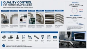
Neither method removes the need to inspect the tube section. State the allowable ovality, minimum wall thickness where relevant, and surface requirements. Specify how ovality is calculated so the supplier and inspector use the same denominator and measurement locations.
Compare incoming stock with samples from the formed region. Tool support, setup, material condition, and geometry all require consideration. Request measured results: a photograph alone cannot establish acceptable ovality or wall thickness.
Springback and Repeat-Part Inspection
Measure after forming loads and clamps are released. Compensation settings help address systematic deviation, but they do not prove that material variation or setup errors have disappeared.
Inspect several consecutive parts under the agreed conditions. Record material batch, tooling, settings, and measurement results. For rotary draw vs roll bending trials, use the same acceptance criteria rather than comparing one supplier’s best sample with another supplier’s unadjusted first trial.
Compare Total Production Cost and Cycle Time
Machine Price and Tooling Scope
Compare complete quotations: machine configuration, tooling, installation, training, inspection needs, and any secondary operations. The lower machine price may exclude tooling needed for your actual range of parts.
For a small product family, count the required setups and tooling sets. For a changing product mix, also consider how operators will identify, install, and validate the correct setup.
Loading, Forming, Adjustment, and Inspection
Ask for a timed trial with clear start and end points. Include loading, forming, unloading, and routine checks. Record trimming or other downstream work separately if it takes place at another station.
Maximum axis speed does not establish output per shift. Similarly, the number of rolling passes alone does not establish total production cost. Include handling and inspection time in your comparison.
Batch Size and Product Changeovers
Divide expected setup effort across the actual batch size. A long run and a ten-piece replacement order may favor different arrangements even when their drawings are similar.
Use your planned product mix in the comparison. Specify shift length, operator involvement, inspection frequency, and the number of changeovers. Without these conditions, a quoted pieces-per-hour figure has limited value.
How ZR Machine Specifications Fit the Decision
DW-Series Tube Bending Equipment
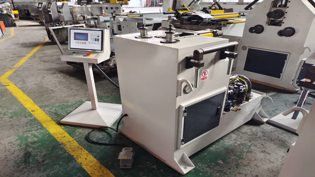
ZR’s supplied DW38CNC-3A-1S documentation lists servo-controlled feeding, rotation, and bending, together with programmable springback compensation. Its listed maximum tube capacity is 38 mm outside diameter × 2 mm wall thickness for carbon steel. That rating is a screening specification, not approval for every material, radius, or part shape.
For defined multi-bend components, review the ZR CNC pipe bending machine range alongside the drawing. Confirm the tooling package, bend sequence, clearances, and sample acceptance conditions for the proposed configuration.
GY-Series Tube Rolling Equipment
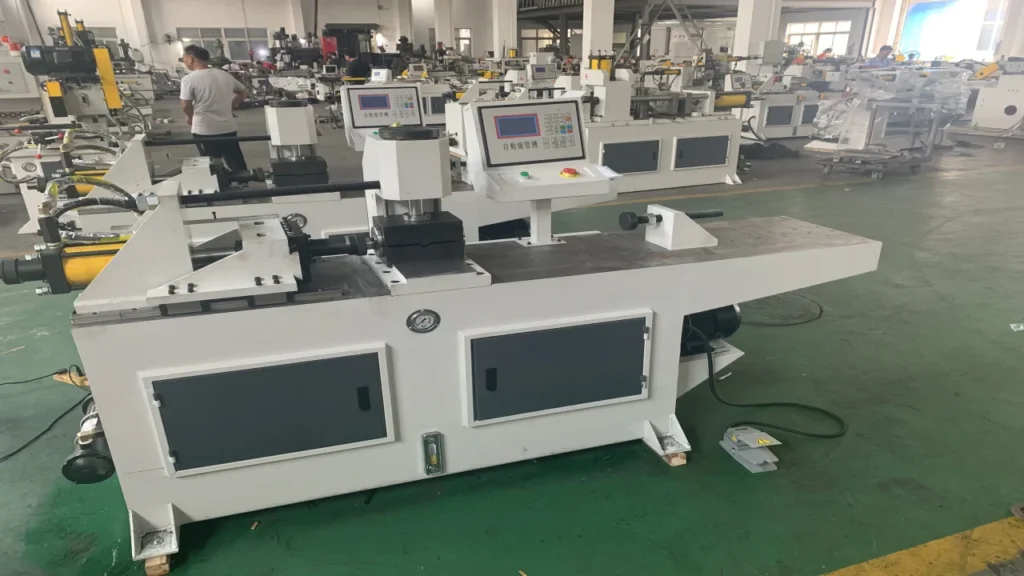
ZR’s supplied GY40NC-3 documentation describes three driven rollers, adjustable curvature, and tooling changes for different supported sections. Its listed maximum tube capacity is 40 mm outside diameter × 2 mm wall thickness for carbon steel. It also describes an asymmetric side-roller arrangement intended to reduce straight end sections, not eliminate them under every condition.
For arcs and circular components, review the ZR tube rolling machine range. Request confirmation of the achievable profile, remaining end sections, tooling, and trial procedure. The DW and GY capacity figures alone do not establish which will make your component better.
What to Send Before Requesting a Recommendation
Provide a drawing or model with:
- Material grade and condition, outside diameter, and wall thickness.
- Radii with their reference clearly marked, angles, straight lengths, and end geometry.
- Dimensional tolerances, surface requirements, and mating or assembly conditions.
- Batch quantity, shift requirements, and expected product changeovers.
- Current defects, if you are replacing an existing process.
Ask the supplier to return a proposed process, tooling scope, and sample-inspection plan. Agree which dimensions will be measured and what constitutes acceptance before the trial. Confirm trial timing and commercial terms separately; do not assume sample production is included before an order.
Frequently Asked Questions
Is roll bending the same as roll forming?
Terminology varies. Here, roll bending means curving an existing tube or section through rollers. Roll forming commonly refers to progressively shaping strip or sheet through successive roll stations. Specify the incoming material and desired component when discussing equipment.
Does changing the radius require new tooling?
Rotary draw bending normally requires compatible bend tooling for a different nominal radius. Roll bending may achieve another radius by changing settings within the supported range. A change in tube diameter or cross-section can still require different tooling for either method.
Can roll bending produce thin-walled tube components?
It can be considered, but suitability depends on the material, diameter-to-wall relationship, radius, support, and acceptance criteria. Request representative samples and section measurements. Neither a blanket rejection of thin-wall rolling nor an unconditional promise is sufficient.
Can one machine perform both rotary draw and roll bending?
Some systems are configured for both. Confirm the exact machine configuration, tooling, control functions, and component clearances. A generic CNC designation does not establish combined capability.
Which method is more economical for small batches?
Compare the cost of making the required geometry, including tooling, setup, handling, trimming, and inspection. Existing suitable tooling can change the economics. Neither method is automatically cheaper for every small order.
How should you compare samples made by the two methods?
Use equivalent stock and the same drawing, inspection method, and acceptance limits. Check released geometry, section condition, surface finish, and repeatability across several parts. Record cycle boundaries and any secondary work needed to obtain the accepted component.
Send your drawing and production requirements to ZR’s contact team to discuss rotary draw vs roll bending, the proposed tooling, and the checks needed before accepting a machine configuration.