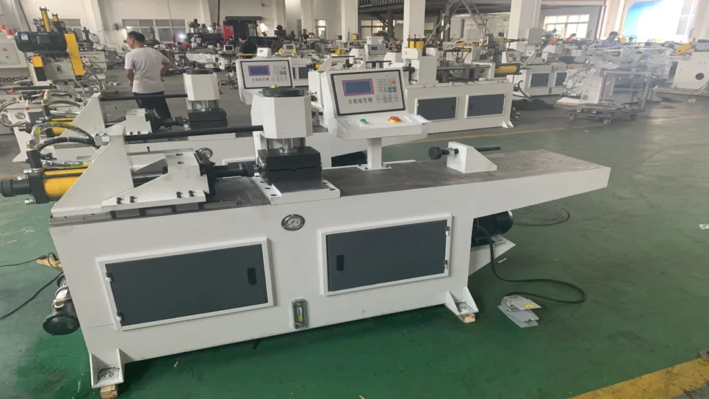
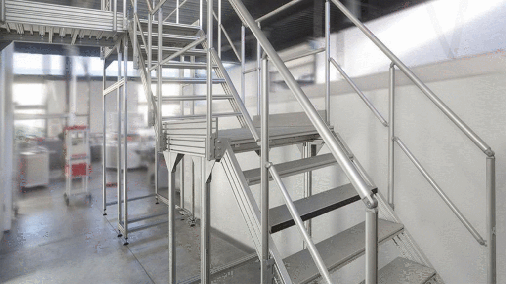
Aluminum profile bending is used to form extruded sections for frames, equipment structures, transport components, architectural parts, and custom assemblies. A profile may look easy to bend because aluminum is relatively formable, but an irregular cross-section can respond very differently from a round tube.
Successful production depends on the complete profile drawing, material condition, wall thickness, bend radius, number of bends, tooling space, and required appearance. You should therefore select the bending machine and tooling from the actual cross-section instead of choosing a model from the profile height alone.
What Is Aluminum Profile Bending?
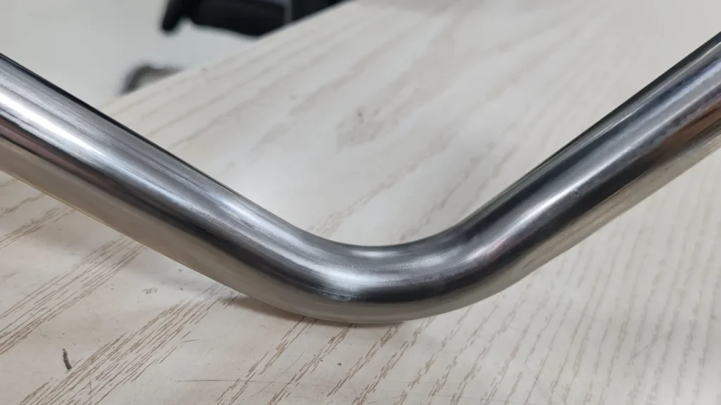
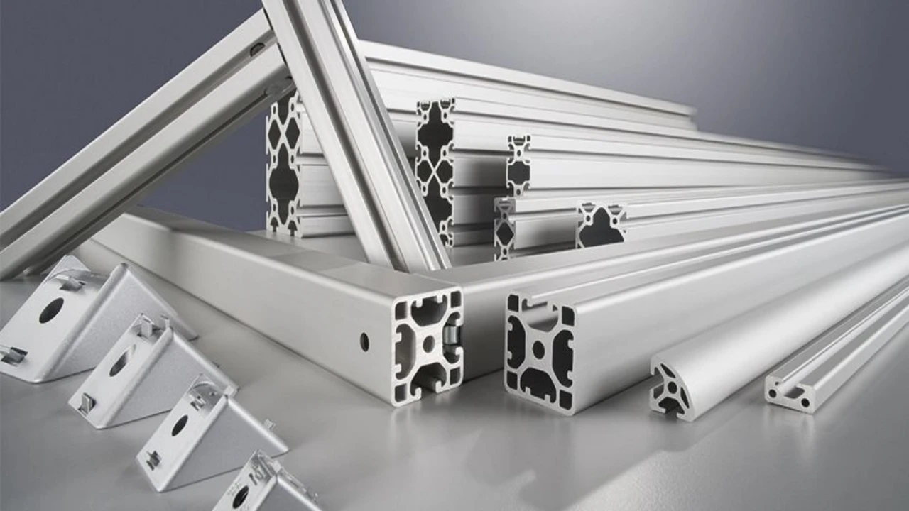
Aluminum profile bending changes a straight extruded section into a controlled curve or a multi-bend three-dimensional shape. Unlike a round tube, an aluminum profile may include several walls, ribs, cavities, slots, lips, and asymmetrical features. These elements affect how the section carries force during forming.
During the process, one side of the profile is stretched while the opposite side is compressed. The section may also rotate, twist, flatten, wrinkle, or move away from the intended path if the tooling does not support the geometry. A process that works for one extrusion may not work for another extrusion with the same nominal height.
For this reason, aluminum profile bending should be treated as an application-engineering task. The drawing, sample material, required bend sequence, and finished-part inspection criteria all belong in the initial evaluation.
If your project also includes round tubes, compare the profile-specific guidance in this article with our guide to the tube bending process. The two applications can use related equipment, but the cross-section and tooling decisions are not interchangeable.
Aluminum Profile Bending vs. Aluminum Tube Bending
Round tubes usually have a consistent wall around the circumference. Aluminum profiles may contain hollow chambers, ribs, slots, thin lips, and unequal wall sections. This difference changes the way the workpiece carries force and makes the profile drawing more important than a single diameter or height.
A round tube can often be described by outside diameter, wall thickness, centerline radius, and bend angle. For an aluminum profile, you also need the complete section orientation, the location of cavities and ribs, the unsupported areas, and the surface that must remain visible after forming.
Use this distinction when comparing machine capacity. An 80 mm-high profile with a small width is not automatically equivalent to an 80 mm round tube. A single bend may fit a 75CNC solution in one profile application, while an 80 mm tube or a multi-bend part may require a 75CNC or a larger model because of forming force, clearance, and finished-part handling.
What Determines Whether an Aluminum Profile Can Be Bent?
Complete cross-section geometry
Profile selection starts with the complete cross-section, not a single outside dimension. You should provide the overall height and width together with wall positions, hollow areas, ribs, openings, lips, and any features close to the bend zone.
An aluminum profile with a height of about 80 mm and a small width may be feasible on a smaller bending machine when the part needs only one bend. A round tube with an 80 mm diameter is a different application because the loading area, tooling envelope, and forming force can be different. Multiple bends can also require more machine space even when the cross-section itself is not large.
Wall thickness and material condition
Common aluminum profile wall thickness is approximately 1.2–3 mm, but the actual design may contain sections that are thinner or thicker. Wall thickness, alloy, temper, extrusion direction, and batch consistency all affect cracking risk, springback, and surface behavior.
Use material from the same manufacturer and, when possible, the same production batch during sample validation. This makes the test result more reliable because different material conditions can produce different springback and deformation behavior.
Bend radius, bend direction, and number of bends
A tight radius increases the risk of cracking, local collapse, wrinkling, and surface marks. A multi-bend part also needs enough clearance for the machine, tooling, profile rotation, and previously formed sections. The final feasibility decision should use the drawing and a sample test rather than a general radius assumption.
Required surface quality
Decorative aluminum profiles may not accept clamp marks, scratches, drag marks, or die impressions. If the part will remain visible, surface requirements should be identified before tooling is designed. Tool cleanliness, lubrication, die condition, and handling method should be controlled together.
Common Problems in Aluminum Profile Bending
Cracking during tight-radius bending
Cracking can occur when the bend radius is too small for the material condition, the wall is thin, or the profile geometry concentrates tensile strain. Material selection, profile orientation, bend radius, forming speed, and tooling support should be evaluated together.
Kinking and local collapse
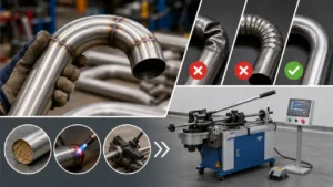
Kinking occurs when the profile loses its intended shape during bending. A wall may fold, or one part of the cross-section may collapse near the bend. Thin sections, unsupported cavities, a small radius, and an unmatched pressure die can increase this risk.
Twisting and section rotation
Asymmetric profiles can rotate during forming because the force is not distributed evenly around the section. The process may require a specially matched clamp die, pressure die, support arrangement, or a different bending sequence.
Surface damage
Clamp marks, scratches, drag marks, cracks, and die impressions can make a product unacceptable. Smooth contact surfaces, correct lubrication, clean tooling, and controlled handling are especially important for visible aluminum extrusions.
For a broader defect checklist, see Zhuoran’s guide to common tube bending defects. The same defect categories can appear in profile work, but the acceptance criteria should follow the profile drawing and finished-part requirements.
How to Select a Machine for Aluminum Profile Bending
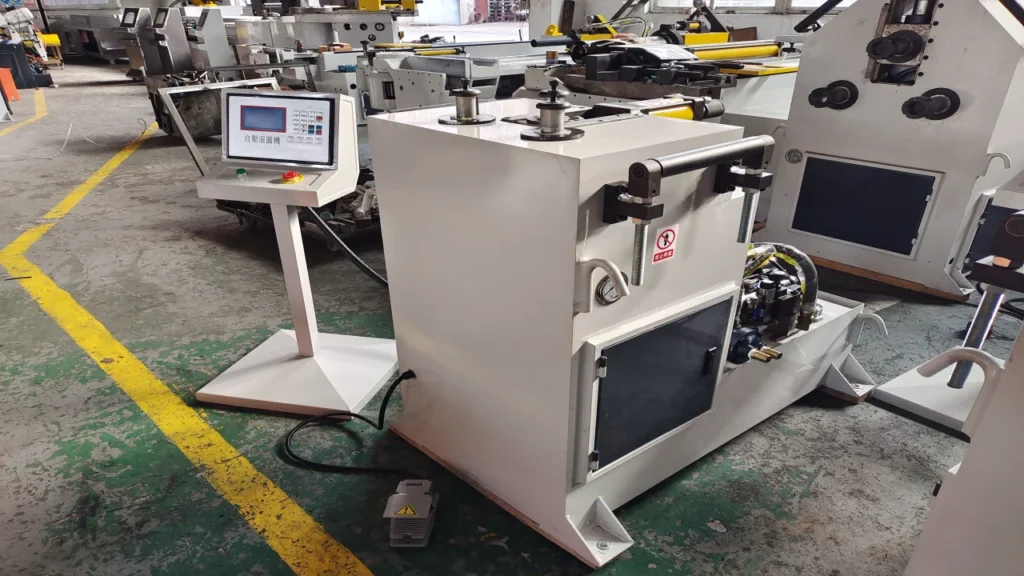
Zhuoran’s 38CNC, 50CNC, and 75CNC are bending machine models that can be used for aluminum tubes and aluminum profiles. The correct model depends on the complete workpiece geometry and forming requirements. A model name should not be treated as a universal guarantee for every profile height, width, diameter, or bend layout.
For larger sections or more complicated forming requirements, Zhuoran can evaluate a larger model. The 130CNC model has a maximum processing size of 130 mm, but the usable range for a specific aluminum profile still depends on the section geometry, wall thickness, bend radius, tooling arrangement, and sample result.
Practical selection experience shows why a complete drawing matters. An irregular aluminum profile with a height of about 80 mm and a small width may be workable on a 75CNC bending machine when only one bend is required. A round tube with an 80 mm diameter, or a part requiring multiple bends, may need a 75CNC or a larger model because the forming space and loading conditions are different.
Application example: Zhuoran recently evaluated an irregular aluminum extrusion with a relatively high section and a small width. The key question was not whether the profile height was close to 80 mm; the engineering decision depended on the complete cross-section, the number of bends, the available clearance, and the required tooling support. A single-bend version may be feasible on a 75CNC, while a round 80 mm tube or a multi-bend version should be evaluated against a 75CNC or larger model.
This example is an engineering-selection reference, not a universal capacity promise. Final confirmation requires the customer drawing, material sample, tooling review, and test bend.
| Workpiece situation | Initial direction | Why sample validation is still required |
|---|---|---|
| Small aluminum profile with a compact section and one bend | Consider 38CNC, 50CNC, or 75CNC according to the drawing | Irregular ribs, cavities, and surface requirements can change the tooling arrangement |
| Profile around 80 mm high with a small width | A 75CNC may be feasible for a single-bend application | Height alone does not describe the full forming load or available clearance |
| Round tube around 80 mm diameter or a multi-bend part | Consider 75CNC or a larger model | Diameter, bend count, rotation, and completed-part length affect machine selection |
| Large aluminum profile or a section approaching the upper range | Evaluate the 130CNC model or another larger solution | The final limit depends on profile geometry and matched tooling, not only the nominal size |
Tooling for Aluminum Profile Bending
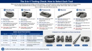
Tooling should be designed as a matched set. Our guide to pipe bending machine tooling explains the broader relationship between the bend die, clamp die, pressure die, mandrel, and wiper die. For an irregular aluminum profile, the contact surfaces must be adapted to the actual extrusion rather than copied from a round-tube setup.
Bend die
The bend die establishes the forming path and bend radius. Its contact shape must match the aluminum profile cross-section and the required finished geometry.
Clamp die
The clamp die holds the profile while the machine forms it. An irregular section may need a custom contact surface so the profile does not slide, rotate, or become locally marked.
Pressure die
The pressure die supports and guides the profile as it moves around the bend die. Pressure-die design and position should be matched to the profile section, wall thickness, bend radius, and forming direction.
Support die
A support die depends on the actual cross-section and forming behavior. It may be needed when a cavity, thin wall, rib, or unsupported feature requires additional local support. The engineering team should confirm the support arrangement from the drawing and sample result.
Mandrel and wiper die
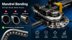
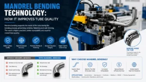
Irregular aluminum profiles generally cannot use a conventional round-tube mandrel arrangement in the same way as a circular tube. Many profile applications are therefore developed without a conventional mandrel, depending on the cross-section and process.
A wiper die is normally used together with a mandrel configuration. In practical tooling design, the mandrel and wiper die are connected decisions: where a mandrel is not used, a conventional wiper-die arrangement is generally not used either. The final choice should be made by the engineering team after reviewing the complete profile.
Springback Compensation in Aluminum Profile Bending
Aluminum can return partly toward its original shape after the bending load is released. Different alloys, tempers, wall thicknesses, profile shapes, and material batches can produce different springback behavior.
Zhuoran’s CNC control system includes a springback compensation function. In a practical development process, you first use consistent material from the same supplier and batch, make a test bend, measure the actual result, and then adjust the compensation value.
For example, if you program a 90-degree bend and the measured result is 88 degrees after unloading, the compensation angle is 2 degrees for that test condition. This value is not automatically universal: changing the material, profile, radius, tooling, or process settings can change the result.
For a wider explanation of test-bend measurement and compensation, see how a CNC tube bending machine works. The same measurement discipline is useful for profile work, but the profile-specific tooling and deformation limits still need separate validation.
What Should the Sample Test Prove?
A sample test should do more than produce one visually acceptable bend. You should use the test to confirm whether the machine, tooling, material, and process can repeat the required result.
- Confirm the profile remains in the required orientation after bending.
- Check the outside surface for clamp marks, scratches, drag marks, and die impressions.
- Check the inside of the bend for wrinkles, local collapse, and loss of cavity shape.
- Measure the bend angle, end position, overall contour, and any critical drawing dimensions.
- Compare the first part with additional parts to identify drift and repeatability problems.
- Record the final machine program, tooling configuration, material batch, and springback compensation value.
If the first sample fails, the next adjustment should be based on the defect. A surface mark may require contact-surface or lubrication changes; twisting may require a different clamp or support arrangement; springback may require a measured compensation update; local collapse may require additional support or a different forming sequence.
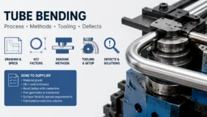
Have an aluminum profile drawing? Send the complete cross-section, material, wall thickness, bend radius, and number of bends before choosing a model. Ask Zhuoran’s engineering team to review the application.
Zhuoran’s Sample-Based Selection Process
- Review the drawing: confirm the complete cross-section, wall thickness, material, bend radius, bend angles, straight lengths, and number of bends.
- Check the incoming material: verify the alloy, temper or material condition, dimensions, surface condition, and batch consistency.
- Evaluate machine size: compare the section geometry and forming space with the 38CNC, 50CNC, 75CNC, 130CNC, or a larger applicable model.
- Design matched tooling: plan the bend die, clamp die, pressure die, and any support arrangement. Confirm whether a mandrel or wiper die is appropriate.
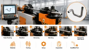
- Run a sample bend: set the feed, rotation, bending angle, speed, pressure, and sequence according to the workpiece.
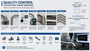
- Measure the result: check the bend angle, profile shape, surface quality, local collapse, twisting, and any cracking or wrinkles.
- Adjust compensation: update the springback compensation value and other process settings based on measured results.
- Confirm repeatability: process multiple samples instead of accepting only one successful part.
What Information Should You Send Before Choosing a Machine?
Send the following information so the engineering team can give a more reliable recommendation:
- Complete aluminum profile cross-section drawing
- Overall height and width of the profile
- Wall thickness, ribs, cavities, slots, and unsupported features
- Alloy, temper, and material batch information
- Required bend radius and bend angle
- Number and sequence of bends
- Finished-part length and straight sections
- Surface-quality requirements
- Expected production volume and automation requirements
- Photos or samples of the profile and finished shape
You can also include the required production cycle, loading direction, unloading method, and whether automatic feeding, cutting, or unloading is needed. These details help the engineering team evaluate not only the bending head but also the surrounding production arrangement.
Frequently Asked Questions
Can all aluminum profiles be bent?
No. Feasibility depends on the complete cross-section, alloy and material condition, wall thickness, bend radius, bend direction, tooling support, and required surface quality. Sample testing is recommended before production.
Is an 80 mm aluminum profile the same as an 80 mm tube?
No. An irregular profile with a height of 80 mm and a small width can behave differently from a round tube with an 80 mm diameter. The complete section, forming force, clearance, tooling, and number of bends must be evaluated.
Can 38CNC, 50CNC, and 75CNC bend aluminum profiles?
Yes. These are Zhuoran bending machine models that can process aluminum tubes and aluminum profiles. The appropriate model depends on the complete drawing, tooling, bend layout, and sample result.
Does an aluminum profile need a mandrel?
Not usually in the same way as a round tube. Many irregular profiles cannot use a conventional round-tube mandrel arrangement. The engineering team should confirm the tooling method from the actual cross-section and process.
When is a support die required?
A support die may be required when the profile needs additional support around a cavity, thin wall, rib, or unsupported feature. The decision depends on the cross-section, wall thickness, bend radius, and forming behavior.
What information should I provide for a machine recommendation?
Provide the complete profile drawing, material and wall thickness, bend radius and angles, number of bends, finished-part length, surface requirements, production volume, and sample or product photos. These details allow Zhuoran to evaluate machine size and tooling more accurately.
Request an Aluminum Profile Bending Evaluation
Share your profile drawing, material details, bend requirements, and sample information. Zhuoran can help evaluate the machine model, tooling arrangement, springback compensation, and sample-test plan for your application.
Technical References for Aluminum Extrusion Information
These references provide background on extrusion drawings, dimensional tolerances, and visual-quality terminology. They do not replace a machine trial or establish Zhuoran machine capacity for a specific profile.
- Drafting Standards for Aluminum Extruded Products — The Aluminum Association.
- Understanding Aluminum Extrusion Tolerances — The Aluminum Association.
- Visual Quality Characteristics of Aluminum Extrusions — The Aluminum Association.
- Processing 101: Aluminum Extrusion Basics — The Aluminum Association.