Introduction: What does ship pipe bending involve?
Ship pipe bending is one step in a larger shipyard piping project. It may be followed by welding, assembly, inspection, pressure testing, installation, and flushing. For that reason, choosing a bending method from the pipe diameter alone is rarely enough.
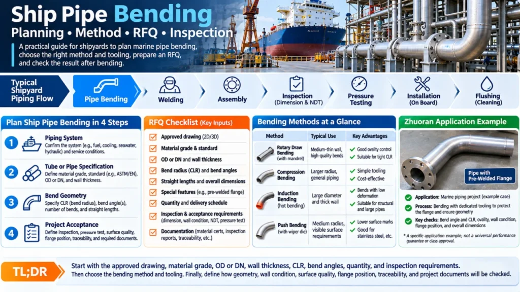
Before you request a machine or fabrication quote, you need to connect four things: the piping system, the tube or pipe specification, the required bend geometry, and the project acceptance requirements. If any of these inputs is missing, a supplier may quote the wrong machine, tooling package, or process.
This guide explains how shipyards can plan marine pipe bending, compare bending methods, prepare an RFQ, and check the result after bending. It also includes a Zhuoran application example involving a pipe with a pre-welded flange. The case is presented as a specific application, not as a universal performance guarantee or class approval.
TL;DR: Start with the approved drawing, material grade, OD or DN, wall thickness, CLR, bend angles, quantity, and inspection requirements. Then choose the bending method and tooling. Finally, define how geometry, wall condition, surface quality, flange position, traceability, and project documents will be checked.
What Does Ship Pipe Bending Include?
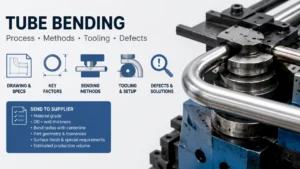
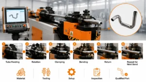
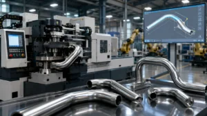
Ship pipe bending normally means forming a straight pipe or tube into the required centerline geometry. For a general overview of forming routes, see Zhuoran’s tube bending process guide. Bending does not automatically include the complete fabrication of a pipe spool, welding, onboard installation, or commissioning.
Bending, spool fabrication, welding, and installation
In a shipyard project, these activities may be connected but they are not the same deliverable:
- Pipe bending forms the required radius, angle, and spatial orientation.
- Pipe spool fabrication may combine cutting, bending, branch connections, flanges, welding, and assembly.
- Welding and NDT create and inspect joints. They require their own procedures, qualifications, and records.
- Onboard installation involves supports, spacing, alignment, connection, cleaning, pressure testing, and flushing.
When you prepare an RFQ, state whether you need a bent pipe, a welded spool, a complete fabrication service, or a bending machine. These requests require different suppliers, equipment, documents, and acceptance criteria.
Ship pipe bending versus general pipe bending
The basic forming mechanics may be similar to other pipe-bending work, but shipbuilding adds system and project constraints. You may need to consider the conveyed fluid, design pressure, design temperature, corrosion environment, access for installation, vibration, space restrictions, and the rules selected for the vessel and piping system.
That is why a generic statement such as “this pipe is bendable” does not complete the engineering decision. You still need to confirm the material condition, geometry, bend radius, surface requirements, and the inspection plan.
Shipyard Piping Systems and Their Different Requirements
Different ship piping systems should not be treated as one identical application. The same pipe-bending method may not be suitable for every material, fluid, pressure range, temperature range, or installation condition.
Machinery piping systems
Depending on the vessel and project, bent sections may appear in systems such as:
- fuel oil and lubricating oil;
- cooling water;
- compressed air;
- steam;
- bilge and ballast water;
- fire protection;
- hydraulic systems; and
- exhaust or emission-control piping.
These examples do not define a universal acceptance rule. The project drawing, system design, vessel type, classification society requirements, and quality plan determine what applies.
IACS Recommendation No. 177 describes quality guidance for machinery piping systems during ship construction and also discusses fabrication, installation, commissioning, function tests, and remedial work. Its bending-related topics include material condition, longitudinal weld seam arrangement, bending radius, surface quality, wall-thickness thinning, roundness, cross-sectional reduction, creasing, angle deviation, shape, and position deviation. You should still confirm the applicable project and class requirements before using any recommendation as an acceptance basis.
System inputs that change the bending decision
Before you compare machines or suppliers, collect at least:
- piping system and service medium;
- design pressure and temperature;
- material grade and material condition;
- pipe OD, DN, or complete profile dimensions;
- wall thickness;
- centerline radius and bend angles;
- weld seam position, if applicable;
- installation space and flange orientation; and
- inspection, traceability, and documentation requirements.
The same outside diameter can require a different process when wall thickness, material condition, bend radius, or flange geometry changes.
How Should You Choose a Bending Method for Ship Pipes?
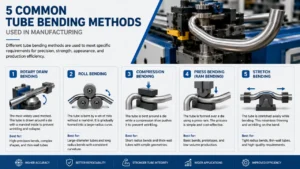
Choose the method from the complete part and project requirements, not from the pipe diameter alone. The main variables are material, OD or DN, wall thickness, CLR, bend angle, number of bends, production volume, surface requirements, available tooling, and the applicable project rules.
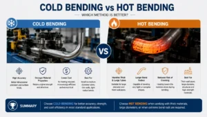
Cold bending and rotary draw or mandrel bending
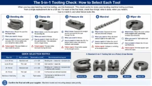
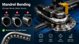
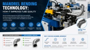
Cold bending is often considered when the material and geometry can be formed without unacceptable cracking, flattening, thinning, or distortion. Rotary draw bending uses a bend die, clamp die, pressure die, and often a collet. For tighter radii or more difficult thin-wall bends, a mandrel and wiper die may be evaluated to support the tube and reduce deformation.
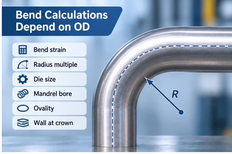
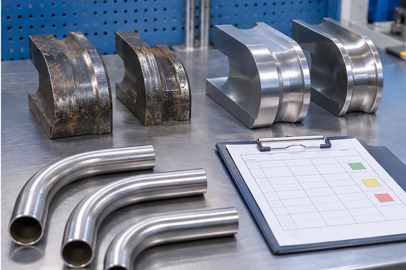
The tooling decision depends on more than the pipe OD. CLR, wall thickness, material, bend angle, straight length, surface requirements, and the distance to a flange or other feature all affect the setup. A supplier should explain why the proposed tooling fits the actual part.
Roll bending and large-radius forming
Roll bending can be considered when the part requires a larger or more continuous curvature rather than a series of tight rotary-draw bends. The required machine and roller arrangement depend on the section shape, material, wall thickness, curvature, and dimensional tolerance.
For shipbuilding work, do not assume that a roll-bending solution for a structural section is interchangeable with a rotary-draw solution for a machinery pipe. The part geometry, support method, and inspection plan are different.
Hot bending and induction bending
Hot bending and induction bending introduce thermal conditions that must be controlled and documented. The selected process may affect material properties, wall-thickness distribution, heat treatment, surface condition, and inspection requirements.
ISO 15590-1:2024 is a useful example of why scope matters. The official ISO description addresses factory induction bends for pipeline transportation systems in the petroleum and natural gas industries. It applies to a defined class of seamless and welded unalloyed or low-alloy steel pipe and does not cover bends made by other manufacturing processes. It should not be presented as a universal standard for every ship pipe or every marine bending method.
A practical method-selection checklist
Ask the supplier to connect each recommendation to your part data:
| Input | Why it matters |
|---|---|
| Material grade and condition | Affects forming force, work hardening, springback, cracking, and surface behavior |
| OD/DN and wall thickness | Affects machine capacity, tooling, support, and deformation risk |
| CLR and bend angle | Affects forming difficulty and tooling requirements |
| Number of bends and rotation angles | Affects axes, programming, collision risk, and cycle time |
| Flanges or welded features | Affects clamping, clearance, protection, and orientation control |
| Quantity and changeover frequency | Affects manual, automatic, or line-level automation |
| Inspection and traceability | Affects sensors, records, barcode/QR integration, and acceptance documents |
RFQ Inputs for Ship Pipe Bending
The best RFQ gives the supplier enough information to evaluate the part, tooling, machine, automation, testing, and delivery boundary in one review.
Drawing and geometry data
Provide a controlled 2D drawing or 3D STEP file whenever possible. The package should show:
- pipe or tube dimensions;
- centerline geometry;
- bend angles and CLR for each bend;
- straight lengths and bend-to-bend distances;
- rotation angles between bend planes;
- bend sequence and end orientation;
- flange, hole, sealing-face, and end-forming details;
- critical tolerances; and
- no-contact or protected surfaces.
For square, rectangular, or special profiles, provide the complete cross-section, not only a nominal “diameter.”
Material and system data
State the exact material grade, condition, applicable material standard, service medium, design pressure, design temperature, and any weld-seam requirements. “Marine grade” alone is not enough for machine or process selection.
Production and acceptance data
Include planned quantity, batch size, shifts, target cycle time, allowable changeover time, loading method, unloading method, surface requirements, inspection frequency, traceability, and required documentation.
Machine and tooling scope
Ask the supplier to separate the quotation into:
- machine body and control system;
- bend die, clamp die, pressure die, mandrel, and wiper die;
- automatic feeding and tube rotation;
- cutting or end-forming modules;
- flange-specific clamping or protection;
- barcode or QR-code reading;
- vision-based position recognition;
- inspection and NG sorting;
- installation, training, trial bending, FAT/SAT, packing, and delivery.
Zhuoran’s project information also follows this principle: the final configuration depends on the drawing, material, tube size, production volume, automation requirements, inspection criteria, and agreed project scope. Optional modules must not be described as standard on every machine.
What Must Be Checked After Bending?
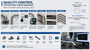
After bending, check the dimensions and surfaces that affect fit, flow, sealing, strength, and the next manufacturing step. The exact limits should come from the approved drawing, project quality plan, applicable rule, or technical agreement.
Geometry and flow-related checks
Typical checks include:
- bend angle;
- centerline radius;
- bend position;
- end position;
- flange orientation;
- roundness or ovality;
- cross-sectional reduction; and
- straight lengths between bends.
Material and surface checks
Depending on the material and application, inspect:
- wall-thickness reduction;
- cracks;
- wrinkles or creasing;
- flattening or collapse;
- scratches and dents;
- pressure or clamp marks;
- sealing-face condition; and
- cleanliness or contamination.
Bending inspection is not the whole piping acceptance
Do not combine every quality activity into one “bending inspection” label. Material certificates, welding procedures, welder qualification, NDT, pressure testing, pipe supports, onboard installation, cleaning, and flushing may require separate controls and records.
This separation makes the RFQ clearer. It also helps you assign responsibility when a bent part is dimensionally correct but the completed piping assembly still requires additional work.

How Should You Evaluate Ship Pipe Bending Capacity?
Evaluate capacity with the actual part and a defined acceptance rule. A machine’s maximum nominal diameter or an ideal cycle time does not equal good output for every ship pipe.
Use a good-output calculation
For production planning, Zhuoran’s tube-processing evaluation framework uses the following general relationship:
“text Good Output = (3,600 × A × Y) ÷ T “
Where:
- A is the operating-time ratio;
- Y is the good-part yield; and
- T is the average cycle time in seconds per part, including normal loading and unloading.
For example, if a part has a 30-second average cycle time, the operating-time ratio is 95%, and the good-part yield is 99%, the estimated good output is approximately 112.9 parts per hour. This is a planning calculation, not a guaranteed shipyard production rate.
Validate the production assumptions
Ask the supplier to record the conditions behind the number:
| Validation item | What to record |
|---|---|
| Continuous-run duration | Test duration and shift conditions |
| Planned quantity | Target quantity for the test |
| Actual quantity | Quantity completed during the run |
| Good quantity | Quantity meeting the agreed inspection criteria |
| NG quantity | Quantity rejected and reason for rejection |
| Average cycle time | Whether loading, unloading, rotation, and inspection are included |
| Unplanned stops | Number and duration of interruptions |
| Alarm count | Alarm type and corrective action |
| Automation coordination | Whether the connected modules worked as intended |
| Inspection and sorting | Measurement method, frequency, and OK/NG logic |
Zhuoran’s internal example records an eight-hour continuous run with planned quantity, actual quantity, good quantity, NG quantity, downtime, alarms, safety stops, and automation coordination. The source record identifies some automation and continuous-run results as simulated, so such data should be presented as a test format or scenario example unless a project-specific test report is approved.
Capacity depends on part complexity
The production rate may change significantly between a simple single-radius part and a multi-bend pipe with a welded flange. Bend count, rotation angle, flange clearance, tooling changes, inspection time, surface protection, and manual handling can all increase the real cycle time.
For that reason, request a trial using the actual material, flange, tooling and inspection criteria before using a capacity figure in a shipyard plan. If the project may become a connected cutting, bending, and inspection workflow, compare the scope with Zhuoran’s tube processing line overview.
Zhuoran Case: Bending a Pipe After Flange Welding
In one Zhuoran ship-pipe bending application supplied for this article, the flange was welded to the pipe before bending. This process addressed a common practical concern: welding a flange after bending can be difficult when access is limited, and flange-hole alignment or flange deformation can create problems during later assembly.
Why flange-first bending can change the process plan
With a conventional bend-first, weld-later route, the operator may need to weld the flange in a confined area. That can make torch access and positioning more difficult. If the flange rotates, distorts, or does not hold the required orientation, the final assembly may require extra alignment work. In a pressure or fluid system, poor mating or a damaged sealing face may also increase leakage risk.
For the disclosed application, the machine was configured to hold a pipe with a pre-welded flange during bending. The stated purpose was to provide stable clamping, reduce pulling or surface damage, and help keep the flange sealing face flat after forming. The practical result to verify on a real project is not only the bend angle, but also flange orientation, hole position, sealing-face condition, and assembly fit.
You can also watch the Zhuoran ship pipe bending application video to see the type of pre-welded-flange bending application discussed in this section.
Case boundary: This is a Zhuoran application example based on the video and technical description supplied for this article. The available information does not establish a universal result for every machine model, flange standard, pipe size, material, tolerance, or classification project. Confirm the actual configuration and trial results with Zhuoran engineers.
Digital Traceability and Position Control for Flanged Pipe Bending
For projects that require batch traceability or a controlled flange orientation, barcode/QR reading and vision-based position recognition can be evaluated as project-specific automation functions.
QR-code and barcode data reading
A code-reading system may be used to associate a workpiece with an order, material batch, drawing revision, bending program, or inspection record. Before specifying this function, define:
- code type and format;
- data fields;
- scanner position;
- connection with the machine control system;
- program-selection logic; and
- data retention and export requirements.
Vision-based rotation recognition and correction
In the disclosed Zhuoran application, the vision function can identify a specified position while the pipe rotates. The system can then correct or calibrate the position before bending. This is especially relevant when a flange, hole pattern, welded feature, or marking must follow a controlled orientation.
The RFQ should still confirm the camera or sensor arrangement, lighting, recognition tolerance, rotation-axis communication, correction logic, and failure handling. These details determine whether the function is a simple position check or part of a larger closed-loop automation system.
Define automation scope clearly
QR/Barcode reading, vision, automatic loading, unloading, inspection, NG sorting, PLC/HMI communication, and MES connectivity should be listed separately. They may be combined into a customized line, but they should not be assumed to be standard on every tube-bending machine.
IACS, Class Rules, and ISO 15590-1: What Applies?
These documents are not interchangeable. Their scope depends on the piping system, vessel or project, manufacturing process, and applicable authority.
IACS Rec.177
Use IACS Rec.177 as a reference for the quality topics and process stages it addresses. It does not replace the rules of the relevant classification society or the project quality plan.
Classification society rules
The actual vessel, system category, design conditions, inspection plan, and class society determine which rules and approvals apply. A machine supplier should not claim class approval without a specific certificate, scope, and project record.
ISO 15590-1:2024
Use ISO 15590-1:2024 only within its stated scope: factory induction bends for pipeline transportation systems in the petroleum and natural gas industries. Do not use it as a general acceptance standard for all marine pipe bending.
How Should You Evaluate a Ship Pipe Bending Machine or Supplier?
Use a drawing and trial-based evaluation. A catalog model name or maximum diameter is not enough to prove that a machine can produce your part.
Questions for a machine supplier
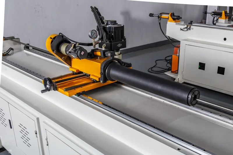
Ask the supplier to confirm the machine and control scope. For a general CNC equipment reference, see the CNC pipe bending machine product page. Then confirm:
- suitable machine series and control system;
- maximum pipe size and wall-thickness range for your material;
- required bend die, clamp die, pressure die, mandrel, and wiper die;
- flange clamping and protected-surface requirements;
- automatic feeding, rotation, cutting, and unloading scope;
- barcode/QR and vision options;
- trial-bending procedure and sample quantity;
- dimensional and surface inspection method;
- FAT/SAT criteria and supplied documents; and
- which items are standard, optional, or project-customized.
Separate standard configuration from project options
Zhuoran’s general CNC equipment framework separates the machine package from project-specific automation. Depending on the model and technical agreement, the evaluation may include:
- CNC control system and machine axes;
- automatic feeding on a CNC model;
- tube rotation for three-dimensional bending;
- bend die, clamp die, pressure die, mandrel, and wiper die;
- multi-stack tooling where the selected machine structure supports it;
- automatic loading and unloading;
- automatic cutting or a separate cutting machine;
- robotic handling;
- online inspection and NG sorting; and
- PLC/HMI or MES integration.
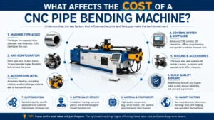
These items should not be copied into a purchase order as if they were all standard on every model. The final scope depends on the part drawing, material, tube size, production volume, cycle time, surface requirements, inspection method, and agreed project scope. A model family such as Zhuoran’s DW CNC series may be evaluated as a starting point, but the model number alone is not a validated maximum diameter, wall-thickness, CLR, or ship-pipe capability statement.
Questions for a fabrication supplier
Ask for evidence related to your actual part, not only a general industry list. The supplier should also explain how the selected tooling and process reduce common tube bending defects:
- material traceability;
- process records;
- dimensional inspection reports;
- surface and sealing-face checks;
- welding and NDT records where applicable;
- pressure-test or system-test responsibility;
- quality-plan alignment; and
- delivery and documentation boundaries.
What should you send to Zhuoran?
Send the finished-part drawing or 3D model, material grade and condition, pipe dimensions, wall thickness, CLR, bend angles, flange details, quantity, target cycle time, tolerances, inspection requirements, and traceability needs. If you need QR/barcode reading or vision-based rotation correction, include the code format, position feature, recognition tolerance, and data-interface requirements.
Engineering review CTA: Send your drawing and tube specifications for an engineering review. Zhuoran can then assess whether the request is better suited to a standalone CNC/NC bending machine, a tooling package, or a customized automation configuration. The final scope should be confirmed by the quotation, trial results, and technical agreement.
Marine Pipe Bending FAQs
What is the difference between ship pipe bending and ship pipe fabrication?
Ship pipe bending forms the pipe geometry. Ship pipe fabrication may also include cutting, flange welding, spool assembly, NDT, pressure testing, and installation. Confirm the exact deliverable before requesting a quote.
What information should I send for a ship pipe bending RFQ?
Send the drawing, material grade, OD or DN, wall thickness, CLR, bend angles, bend sequence, rotation angles, flange details, quantity, tolerances, inspection criteria, and required documents.
Can a flange be welded before a pipe is bent?
It can be evaluated for a specific machine and tooling configuration. The Zhuoran case supplied for this article describes bending a pipe after flange welding to address confined-space welding and flange-alignment concerns. The actual part still requires drawing review and trial validation.
Does ISO 15590-1 apply to every marine pipe bend?
No. ISO 15590-1:2024 addresses factory induction bends for pipeline transportation systems in the petroleum and natural gas industries. It is not a universal standard for every marine pipe or every bending method.
Can QR codes and vision positioning be added to a pipe-bending machine?
They can be evaluated as project-specific functions. The exact scanner, camera, control logic, rotation correction, data interface, and failure handling depend on the part and automation scope.
Conclusion
Ship pipe bending should be planned as part of the complete piping and quality workflow. Start with the system, material, drawing, OD/DN, wall thickness, CLR, angles, flange details, quantity, and acceptance requirements. Then compare bending methods and tooling against the actual part.
The Zhuoran flange-first application shows why the process sequence can matter. When a pipe includes a welded flange, clamping, surface protection, hole orientation, sealing-face condition, and assembly fit become part of the bending discussion. Barcode/QR reading and vision-based rotation correction may also be considered when traceability and orientation control are important.
If you are evaluating a ship pipe bending machine or customized automation, send the drawing, material data, flange requirements, inspection criteria, and production target for an engineering review.
References and Sources
- IACS — Recommendation 177 and machinery piping quality — supports the scope and quality topics of machinery piping guidance; it does not prove Zhuoran class approval.
- ISO 15590-1:2024 — supports the official scope of factory induction bends for pipeline transportation systems; it is not a universal marine pipe standard.
- Unison — Rotary Draw Bending Tooling — supports general tooling terminology; it is not a ship-class rule or Zhuoran capability record.
- Zhuoran ship pipe bending application video — linked in the flange-first case section above; publicly approved by the user as an application reference. Model, specifications and measured results remain subject to engineering confirmation.