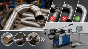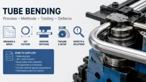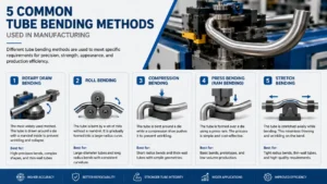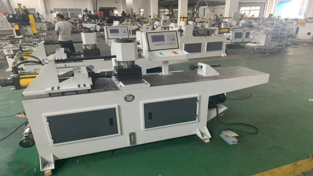
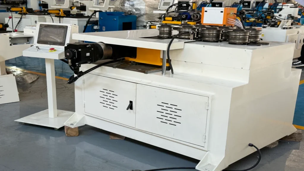
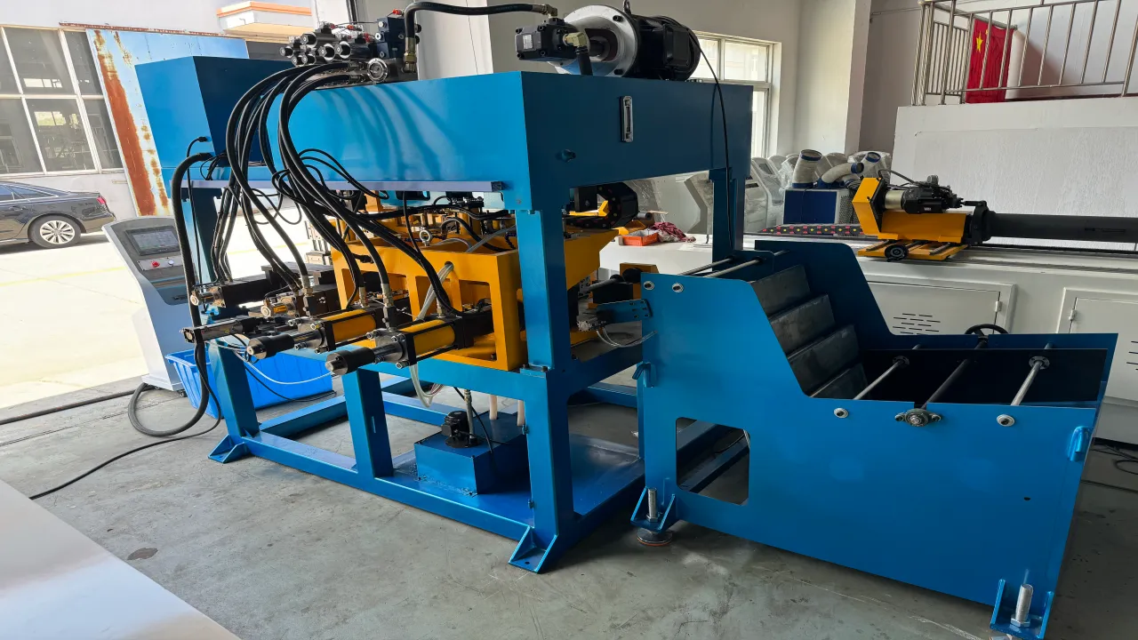
A tube processing line is a coordinated production route for turning tube stock into finished parts. Depending on the product, the line may include cutting, feeding, bending, tube end forming, chamfering, inspection, unloading, and automatic sorting.
If you are planning a new line, the main challenge is not simply choosing several machines. Each station must match the tube material, outside diameter, wall thickness, bend geometry, end requirements, production volume, and inspection standard.
This guide focuses on downstream tube processing lines that start with finished tube stock. It does not describe an ERW tube mill or strip-to-tube production line. Instead, it explains how CNC equipment can be integrated into an automated tube fabrication line and what you should confirm before requesting a quotation.
What Is a Tube Processing Line?
A tube processing line combines several tube manufacturing operations into one coordinated workflow.
A typical route may include:
- Raw tube loading
- Tube cutting
- Automatic feeding
- Tube rotation and positioning
- CNC tube bending
- Tube end forming
- Chamfering or deburring
- Dimensional inspection
- OK/NG sorting
- Finished-part collection
Not every product requires every operation. A simple part may only need cutting and bending. A more complex part may need cutting, multiple bends, end forming, chamfering, inspection, and robotic unloading.
The correct equipment depends on the finished part rather than the machine name. Before selecting a line, you should define:
- Tube material and grade
- Outside diameter and wall thickness
- Tube shape
- Cut length
- Bend radius
- Bend angle
- Number of bends
- Bend sequence
- Tube rotation angle
- End-forming requirements
- Production quantity
- Inspection requirements
- Loading and unloading method
A tube processing line may be designed as a group of stand-alone machines, a connected production cell, or a fully automated line controlled by a central PLC and HMI system.
Which CNC Equipment Can Be Integrated into a Tube Processing Line?
Zhuoran CNC equipment can be integrated into complete tube processing lines and can support automated production configurations. The exact combination depends on the part drawing, tube specifications, production volume, process sequence, and quality requirements.
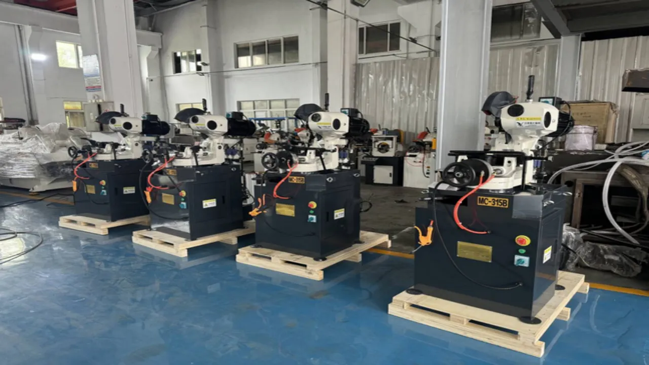
CNC Tube Cutting
A CNC tube cutting station prepares the tube to the required length before bending or other forming operations.
The cutting method should be selected according to:
- Tube material
- Outside diameter
- Wall thickness
- Required cut length
- End-face quality
- Burr limits
- Production speed
- Whether the tube will be bent before or after cutting
Common cutting solutions may include circular saw cutting, blade cutting, rotary cutting, or another project-specific method. Cutting is not automatically included in every tube bending machine quotation. It may be supplied as an integrated cutting module or as a separate pipe cutting machine.
The quotation should identify:
- Cutting machine model
- Cutting method
- Cutting tolerance
- Automatic or manual loading
- Automatic or manual unloading
- End-face requirements
- Chip and burr-control method
- Whether cutting is performed before or after bending
For some parts, the process may begin with a long tube and use a fixed-length cutting operation later in the line. Other products may use pre-cut blanks that are loaded directly into the bending machine.
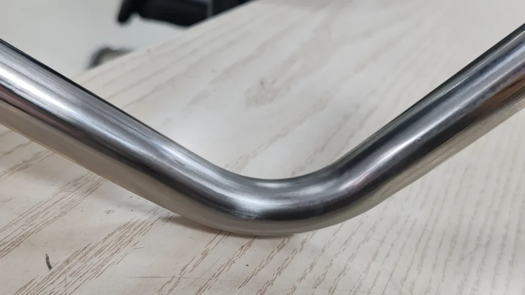
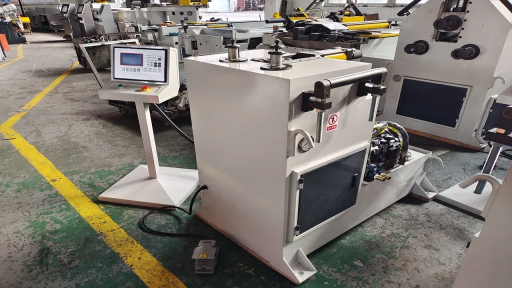
CNC Tube Bending
The CNC bending station forms the tube according to the customer drawing.
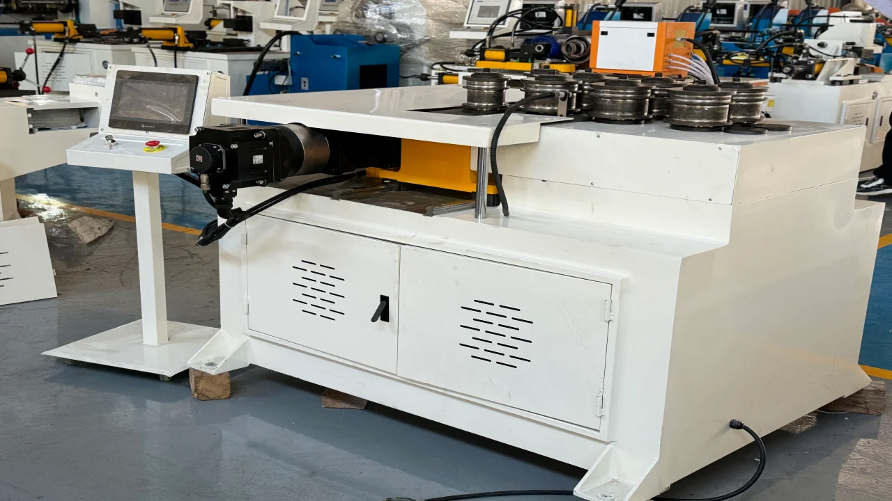
Zhuoran’s CNC bending equipment can be selected from the DW38CNC–DW168CNC series according to the actual tube and part requirements. The correct model cannot be selected from outside diameter alone. Engineers should also evaluate:
- Wall thickness
- Material grade
- Centerline radius
- Bend angle
- Number of bends
- Tube length
- Tube shape
- Required tooling
- Allowable deformation
- Production volume
You can review the main CNC pipe bending machine range before sending your part information.
Automatic feeding is a standard configuration on CNC machine models. Automatic tube rotation, multi-bend programming, and other functions depend on the selected machine configuration and part geometry.
CNC Tube End Forming
Tube end forming changes the geometry at one or both ends of the tube.
Typical end-forming requirements may include:
- Flaring
- Reducing
- Swaging
- Beading
- Expanding
- Necking
- Chamfering
- Special connection profiles
The required process depends on the component design. Some parts need end forming before bending. Others require end forming after bending because the final shape must be controlled relative to the bend position.
A dedicated tube end forming machine can be integrated into the line.
The quotation should state:
- The end-forming operation
- Tooling included
- Number of forming stations
- Forming sequence
- Required tube support
- Changeover method
- Inspection method
- Whether the station is integrated or separate
Chamfering and Supporting Equipment
Some tube parts require chamfering, deburring, marking, drilling, punching, rolling, or additional preparation.
Supporting equipment may include:
- Material racks
- Tube separators
- Long-tube supports
- Automatic loading devices
- Servo feeding units
- Robots
- Finished-part collection systems
- Vision inspection
- Laser measurement
- NG sorting
- PLC and HMI line-control systems
These modules should be treated as part of the line design rather than assumed to be included in every standard machine package.
What Does a Typical Automatic Tube Processing Line Look Like?
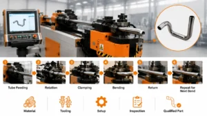
A typical automatic tube processing line may follow this sequence:
Raw Tube → CNC Cutting → CNC Bending → End Forming → Inspection → OK/NG Sorting
A line PLC and HMI coordinate the stations and manage safety interlocks.
A robot may transfer parts between the cutting, bending, end-forming, and inspection stations. The actual route can change according to the product design. For example, some parts may require end forming before bending, while others may need two cutting operations.
A tube cutting and bending line may be suitable when the product requires fixed-length preparation followed by repeatable CNC bending.
Typical Line Structure
| Station | Main function |
|---|---|
| Raw tube storage | Stores tube stock and provides material to the loading system |
| Automatic loading | Transfers tube stock from the rack or material magazine |
| CNC cutting | Produces blanks or performs fixed-length cutting |
| Automatic feeding | Moves the tube into the next station |
| CNC bending | Produces one or more bends |
| End forming | Creates the required tube-end profile |
| Inspection | Checks dimensions, angles, position, and appearance |
| OK/NG sorting | Separates acceptable and non-conforming parts |
| Finished-part collection | Collects and protects completed parts |
| Line PLC/HMI | Coordinates sequence, status, alarms, and interlocks |
The line layout should be created after the process route is confirmed. Adding machines first and defining the process later can create problems with transfer direction, floor space, buffer capacity, cycle time, and operator access.
How Should You Choose the Process Modules for Your Tube Parts?
Start with the finished tube part, not the equipment list.
Material and Tube Grade
Typical tube materials may include:
- Carbon steel
- Stainless steel
- Aluminum
- Copper
- Brass
However, not every machine model is automatically suitable for every material. You should provide the exact material grade and condition whenever possible.
Material affects:
- Required bending force
- Springback
- Surface damage risk
- Wall thinning
- Ovality
- Cracking risk
- Tooling material and coating
- Need for a mandrel or wiper die
For example, a soft copper tube and a high-strength stainless steel tube may have the same outside diameter but require different tooling and process parameters.
Outside Diameter and Wall Thickness
For round tube, provide the complete tube specification:
OD × Wall Thickness
For example:
Ø38 × 1.5 mm
For square, rectangular, or special-profile tube, provide:
- Width
- Height
- Corner radius
- Wall thickness
- Material grade
- Cross-section drawing
Outside diameter alone is not enough to select a tube processing line. The relationship between diameter and wall thickness has a direct effect on forming difficulty.
Bend Radius and Bend Geometry
Provide the centerline radius, or CLR, for every bend.
For example:
- Tube OD: 38 mm
- CLR: 57 mm
- CLR/OD: 1.5D
A small CLR may require stronger tube support and more advanced tooling. The line designer may need to evaluate:
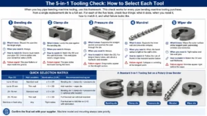
- Bending die
- Clamp die
- Pressure die
- Mandrel
- Wiper die
- Boost bending
- Multi-stack tooling
- Tube rotation and clearance
You should also list every bend angle and bend position. A drawing with only a final outline may not provide enough information for machine and tooling selection.
Number of Bends and Bend Sequence
A part with one 90-degree bend is very different from a part with six bends in multiple planes.
Provide:
- Total bends per part
- Angle of each bend
- Distance between bends
- Bend direction
- Bend sequence
- Rotation angle between bend planes
- Straight lengths between bends
- Final tube-end orientation
For a three-dimensional tube part, the rotation angle between bends is especially important. The line may require CNC tube rotation, multi-axis positioning, or a specific loading orientation.
Tube End Requirements
End forming and cutting should be planned together with bending.
Provide details such as:
- Cut length
- End-face tolerance
- Burr limit
- Chamfer requirement
- Flare
- Reduction
- Bead
- Thread
- Groove
- Expansion
- Sealing surface
- End orientation relative to the bends
If the tube end is used for assembly or sealing, appearance alone may not be sufficient. The end profile may need dimensional inspection with a dedicated gauge.
Production Volume
Production volume influences the automation level.
You should provide:
- Pieces per day
- Pieces per month
- Number of shifts
- Working hours per shift
- Product mix
- Batch size
- Expected changeover frequency
- Required buffer stock
- Target cycle time
A lower-volume project may be better suited to a CNC machine with manual loading and project-specific automation. A stable, higher-volume project may justify a complete line with automatic loading, robotic transfer, inspection, and NG sorting.
The correct decision depends on the complete production requirement rather than the nominal speed of one machine.
How Do You Configure Tooling and the Control System?
A tube processing line normally includes both equipment and tooling. The tooling package should be defined separately in the quotation.
Main Machine and Control System
The quotation should identify:
- Main machine model
- Working range
- Number of controlled axes
- Control system
- PLC functions
- Industrial CNC functions
- Program storage
- Recipe management
- Alarm system
- Safety interlocks
- Communication with other stations
Zhuoran equipment may use a PLC or industrial CNC control system, depending on the machine and project configuration.
The line-level PLC/HMI may be separate from the individual machine control. It can coordinate:
- Station sequence
- Material transfer
- Part-present signals
- Clamp confirmation
- Machine-ready signals
- Fault alarms
- Inspection results
- OK/NG routing
- Emergency-stop circuits
Bending Tooling
Typical bending tooling may include:
- Bending die
- Clamp die
- Pressure die
- Mandrel
- Wiper die
- Multi-stack tooling
- Gripping or loading tooling
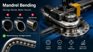
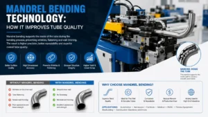
The bending die, clamp die, and matching tooling should be identified in the quotation. Mandrels and wiper dies are not automatically required for every tube or bend.
The need for a mandrel or wiper die depends on:
- Tube material
- Outside diameter
- Wall thickness
- CLR
- Bend angle
- Surface requirements
- Ovality requirement
- Wall-thinning limit
- Wrinkle tolerance
You can review the principles of pipe bending machine tooling when preparing your tooling requirements.
Multi-Stack Tooling
Multi-stack tooling allows one machine to use different bending tools for different tube sizes or bend radii.
It may be useful when:
- One machine processes several tube sizes
- Multiple bend radii are required
- Product changeover must be reduced
- Several tools need to remain available on the same machine
Multi-stack tooling is available for machine models configured for this function. The tooling dimensions should be designed according to the actual customer product.
The quotation should specify:
- Number of tool stacks
- Tube sizes
- Bend radii
- Tool-change method
- Tool storage
- Changeover time
- Included and excluded tooling
What Automation Options Can Be Added to the Line?
An automated tube processing line may include the following functions:
- Automatic loading
- Automatic feeding
- Automatic tube rotation
- Automatic cutting
- Automatic unloading
- Robotic handling
- Inline inspection
- NG sorting
- Finished-part collection
- Integrated line control
These functions can be configured individually or combined into a complete production line according to:
- Tube dimensions
- Tube material
- Part geometry
- Production volume
- Quality requirements
- Factory layout
- Operator requirements
- Required traceability
Zhuoran CNC equipment can support automated production configurations and can be integrated with other CNC stations. However, automatic cutting, automatic unloading, robots, inspection systems, and other auxiliary equipment should be clearly identified as standard, optional, or project-specific.
Automatic feeding is a standard configuration on CNC machine models. Other automation modules depend on the selected machine and line design.
For a broader overview, see how automation is changing tube processing.
Typical Automation Modules
| Module | Possible function |
|---|---|
| Material rack | Stores raw tubes and keeps them accessible to the loading system |
| Automatic loading rack | Transfers tubes to the first processing station |
| Single-tube separator | Releases one tube at a time |
| Servo feeding | Controls tube position and feed length |
| Robot loading | Transfers tubes between stations |
| Automatic unloading | Removes finished parts from the machine |
| Finished-part collection | Separates or stores completed parts |
| Inspection unit | Checks dimensions or part presence |
| NG sorting | Diverts non-conforming parts |
| PLC/HMI | Coordinates the entire line |
Long tubes may require dedicated supports and feeding mechanisms to prevent sagging, vibration, or unstable positioning.
Should You Use Stand-Alone Machines, a Connected Cell, or a Complete Line?
| Configuration | Suitable when | Main advantage | Main limitation |
|---|---|---|---|
| Stand-alone machine | Product mix is broad or batch sizes are small | Flexible and easier to change | More manual handling |
| Connected cell | Two or more operations need controlled transfer | Better flow and less handling | Requires interface planning |
| Complete automated line | Product sequence is stable and volume is consistent | High process integration and traceability | Higher design complexity |
Stand-Alone Equipment
A stand-alone CNC bending machine may be appropriate when you process:
- Several tube sizes
- Different materials
- Many product families
- Small or medium batches
- Frequent tooling changes
- Products with different process routes
This arrangement gives you flexibility, but operators may need to transfer material between cutting, bending, and end-forming stations.
Connected Production Cell
A connected cell links two or more machines with transfer equipment.
Examples include:
- Cutting plus bending
- Bending plus end forming
- Bending plus inspection
- Cutting, bending, and unloading
A connected cell can reduce manual handling while keeping more flexibility than a complete line.
Complete Automated Line
A complete line may combine:
- Raw material storage
- Automatic loading
- CNC cutting
- CNC bending
- End forming
- Chamfering
- Robotic transfer
- Inspection
- OK/NG sorting
- Finished-part collection
- Line-level PLC/HMI control
A complete line is more suitable when the part design and production sequence are stable. It should be designed around the actual product and factory layout.
How Should You Evaluate Capacity, Cycle Time, and Changeover?
Do not evaluate a tube processing line only by bending speed.
The actual production rate also includes:
- Loading
- Feeding
- Tube rotation
- Clamping
- Bending
- End forming
- Inspection
- Unloading
- NG handling
- Buffer transfer
- Changeover
- Operator intervention
A simple planning formula is:
Saleable output = Nominal rate × Operating time × Utilization × YieldThis is a planning model, not a guaranteed production result.
A part with one bend may have a very different cycle time from a part with six bends, two end-forming operations, and a full inspection sequence.
What to Confirm During a Cycle-Time Review
Ask the supplier to define:
- Part used for the calculation
- Number of bends
- Material and tube size
- Loading method
- Unloading method
- Inspection steps
- Changeover assumptions
- Operator involvement
- Buffer assumptions
- Whether the result refers to nominal or saleable output
For complex parts, a cycle-time simulation or trial run is more reliable than a general machine-speed statement.
Example: 8-Hour Continuous-Run Validation
The following example is based on Zhuoran-provided production-validation data. The source record identifies the automation and continuous-run results as simulated. It should therefore be used as an example validation record, not as a universal performance guarantee for every machine or product.
| Validation item | Result |
|---|---|
| Continuous run duration | 8 hours |
| Planned quantity | 1,200 pcs |
| Actual quantity | 1,185 pcs |
| Good quantity | 1,182 pcs |
| NG quantity | 3 pcs |
| Unplanned stops | 1 |
| Total downtime | 5 minutes |
| Alarm count | 1 |
| Safety-stop count | 0 |
| Abnormal heat or noise | None observed in the simulation |
| Automation coordination | Passed in the simulation |
| Inspection and sorting | Passed in the simulation |
| Continuous-run result | Example passed; final acceptance depends on the agreed criteria |
The main calculated results are:
- First-pass yield: 99.75%
- Planned quantity completion: 98.75%
- Scheduled-time good output: 147.75 pcs/hour
- Scheduled running-time ratio: 98.96%
The first-pass yield is calculated as:
First-pass yield = Good quantity ÷ Actual quantity × 100%

                 = 1,182 ÷ 1,185 × 100%

                 = 99.75%
The planned quantity completion rate is:
Planned quantity completion
= Actual quantity ÷ Planned quantity × 100%

= 1,185 ÷ 1,200 × 100%

= 98.75%
The scheduled-time good output is:
Scheduled-time good output
= Good quantity ÷ Scheduled test time

= 1,182 ÷ 8

= 147.75 pcs/hour
The scheduled running-time ratio is:
Scheduled running-time ratio
= (Scheduled minutes − Downtime) ÷ Scheduled minutes × 100%

= (480 − 5) ÷ 480 × 100%

= 98.96%
Because the test included five minutes of downtime, 147.75 pcs/hour should be described as good output per scheduled hour. It should not be confused with theoretical machine speed or net running rate.
The final acceptance result should still be confirmed with the customer’s actual tube material, drawing, tooling, inspection method, and agreed FAT/SAT procedure.
How Are Quality Control and OK/NG Sorting Planned?
Quality control should be connected to the customer drawing and acceptance requirements.
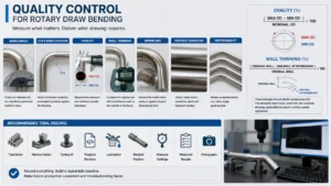
Typical inspection items may include:
- Cut length
- Bend angle
- Bend position
- Straight length
- End-form dimensions
- Tube-end orientation
- 3D centerline position
- Ovality
- Wall thinning
- Wrinkles
- Cracks
- Scratches
- Dents
- Burrs
- Part presence
Inspection can be performed manually or automatically.
Possible systems include:
- Calipers
- Angle gauges
- Dedicated fixtures
- Profile gauges
- Vision inspection
- Laser measurement
- Dimensional inspection systems
- Part-presence sensors
- Automatic NG sorting
The inspection method should match the required tolerance. A simple manual check may be enough for a low-volume part. A high-volume line may need automatic inspection and traceability.
Example: Dimensional and Forming Inspection Record
The following example is based on the provided Zhuoran validation data.
| Inspection item | Requirement | Example result | Method | Status |
|---|---|---|---|---|
| Cut length | 500 ±0.20 mm | 500.08 mm | Digital caliper / length gauge | Pass |
| Bend angle | 90 ±0.30° | 90.12° | Angle measuring instrument | Pass |
| Bend position | 150 ±0.30 mm | 150.11 mm | Dedicated gauge / CMM | Pass |
| Straight length | 150 ±0.30 mm | 150.11 mm | Caliper / dedicated gauge | Pass |
| Tube-end position | Deviation ≤0.50 mm | 0.24 mm | CMM / dedicated gauge | Pass |
| End-form dimension | Outside diameter Ø42.00 ±0.20 mm | Ø42.08 mm | Dedicated gauge / caliper | Pass |
| 3D centerline profile | Profile deviation ≤1.00 mm | 0.46 mm | CMM / laser measurement | Pass |
| Ovality | ≤3.0% | 1.8% | Outside micrometer / dedicated gauge | Pass |
| Wall thinning | ≤10.0% | 6.2% | Ultrasonic thickness gauge / section inspection | Pass |
| Wrinkles | No visible wrinkles permitted | None observed | Visual inspection / dedicated gauge | Pass |
| Cracks | No cracks permitted | None observed | Visual inspection; additional testing if required | Pass* |
| Scratches and dents | Within approved sample limit | No excessive defects observed | Visual comparison / sample comparison | Pass |
| Burr height | ≤0.10 mm | 0.04 mm | Profile gauge / magnified inspection | Pass |
| Surface quality | Consistent with approved sample | Consistent with sample | Visual comparison | Pass |
* Crack acceptance should be confirmed according to the customer’s drawing, material requirements, and agreed inspection method. Visual inspection alone may not be sufficient for every application.
Example: Ovality Calculation
For a nominal tube outside diameter of 38 mm:
- Maximum measured outside diameter: 38.30 mm
- Minimum measured outside diameter: 37.616 mm
- Nominal outside diameter: 38 mm
Ovality = (Dmax − Dmin) ÷ Dnominal × 100%

Ovality = (38.30 − 37.616) ÷ 38 × 100%

        = 1.8%
The example result is within the stated target of 3.0%.
Example: Wall-Thinning Calculation
Assume:
- Original wall thickness: 1.500 mm
- Minimum wall thickness after bending: 1.407 mm
Wall thinning = (t0 − tmin) ÷ t0 × 100%

Wall thinning = (1.500 − 1.407) ÷ 1.500 × 100%

              = 6.2%
The example result is within the stated target of 10.0%.
These figures should not be treated as universal limits for every material, tube size, bend radius, or tooling configuration. Actual limits should be agreed with the customer.
During line design and SAT planning, machine guarding and risk-reduction requirements should be reviewed according to applicable local regulations and project standards. For general reference, see OSHA machine-guarding requirements and ISO 12100 principles for machinery risk assessment.
How Do FAT, SAT, Installation, and Training Work?
A complete project should define both technical acceptance and service responsibilities.
Factory Acceptance Test
FAT is normally completed before shipment.
The FAT may review:
- Product quality
- Machine functions
- Continuous operation
- Automation coordination
- Actual production takt
- Fault alarms
- Safety functions
- Part transfer
- Inspection and sorting
- Tooling performance
The final FAT procedure should identify:
- Test material
- Test drawing
- Sample quantity
- Inspection tools
- Acceptance tolerances
- Test duration
- Required documents
- Responsibility for approval
Site Acceptance Test
SAT is completed after installation at the customer’s site.
It may include:
- Machine installation
- Line connection
- Utility verification
- Program loading
- Tooling installation
- Operator operation
- Production trial
- Safety verification
- Automation communication
- Inspection confirmation
- Final sample approval
The exact SAT requirements should be confirmed in the technical agreement.
Installation and Training
Installation and training should be listed in the quotation rather than assumed.
The agreement should clarify:
- Remote or on-site installation
- Installation duration
- Customer preparation requirements
- Electrical and air connections
- Foundation or floor requirements
- Operator training
- Maintenance training
- Programming training
- Travel and accommodation responsibility
- Training documents
Transportation, delivery time, and Incoterms should also be clearly stated in the quotation.
What Should Be Included in a Tube Processing Line Quotation?
A tube processing line quotation should separate included items from optional and project-specific items.
| Item | Typical Zhuoran planning status |
|---|---|
| Main machine | Selected from the DW38CNC–DW168CNC series according to the part |
| Control system | PLC or industrial CNC, depending on configuration |
| Bending die | Included according to the quoted tooling scope |
| Clamp die | Included according to the quoted tooling scope |
| Pressure die | Configured according to the bending system and tooling requirements |
| Mandrel | Optional, according to material and forming requirements |
| Wiper die | Optional, according to material and forming requirements |
| Multi-stack tooling | Available for suitably configured machine models |
| Automatic feeding | Standard configuration on CNC machine models |
| Tube cutting | Optional; integrated module or separate cutting machine |
| Automatic unloading | Optional; unloading mechanism or robot |
| Inspection system | Project-specific |
| NG sorting | Project-specific |
| Installation | Confirmed according to the agreement |
| Training | Confirmed according to the agreement |
| Transportation | Confirmed in the quotation and Incoterms |
| Warranty | Coverage and exclusions confirmed in the agreement |
| Extra tooling | Listed separately |
| Automation equipment | Listed separately unless included in the project scope |
The quotation should also identify excluded items. These may include:
- Additional tooling
- Extra automation equipment
- Transportation
- Installation
- Factory utilities
- Special inspection equipment
- Customer-provided fixtures
- Special software or communication interfaces
For a structured request, use the tube bending machine RFQ checklist as a starting point.
What Information Should You Send for a Tube Processing Line Proposal?
A supplier cannot properly evaluate a line from the tube diameter alone.
Product and Drawing Information
Send:
- 2D drawing
- 3D STEP file
- Finished-part dimensions
- Bend locations
- Bend angles
- Bend radii
- Straight lengths
- Tube-end orientation
- Critical dimensions
- Tolerances
- Surface requirements
Tube Information
Provide:
- Material grade
- Material condition
- Outside diameter
- Wall thickness
- Wall-thickness tolerance
- Tube shape
- Tube length
- Surface condition
- Supplied form, such as straight tube or coil
Process Information
Define:
- Cutting sequence
- Bending sequence
- End-forming sequence
- Chamfering requirements
- Number of bends
- Rotation angle
- Loading direction
- Unloading direction
- Required inspection points
- OK/NG handling
Production Information
Provide:
- Pieces per day
- Pieces per month
- Working shifts
- Product mix
- Batch size
- Target cycle time
- Required changeover time
- Expected automation level
- Available operators
Factory Information
The supplier may also need:
- Power supply
- Compressed-air requirements
- Floor space
- Floor loading
- Factory layout
- Material flow
- Safety requirements
- Network or MES requirements
- Robot access
- Finished-part storage area
Acceptance Information
Define:
- Sample trial requirements
- Sample quantity
- Inspection tools
- Dimensional tolerances
- Surface requirements
- FAT procedure
- SAT procedure
- Repeatability test
- Continuous-run test
- Safety test
- Required documentation
For engineering support, you can use Zhuoran’s design and engineering service.
Which Applications Can Use a Tube Processing Line?
A tube processing line may be considered for many industries and product types, including:
- Automotive and exhaust components
- HVAC and refrigeration parts
- Heat exchanger assemblies
- Hydraulic and pneumatic tubes
- Furniture frames
- Fitness equipment
- Stainless steel assemblies
- Aluminum tube components
- Copper tube assemblies
- General industrial tube parts
Each application creates different process requirements.
For example:
- Automotive parts may require repeatable multi-bend geometry and end forming.
- HVAC parts may require cutting, bending, and tube-end preparation.
- Heat exchanger components may require accurate spacing and repeated production.
- Furniture tubes may place greater emphasis on appearance and surface protection.
- Hydraulic tubes may require strict dimensional and end-form control.
These are application scenarios, not automatic guarantees that one line configuration is suitable for every product. The equipment and tooling must still be checked against the actual drawing and material.
Frequently Asked Questions About Tube Processing Lines
What is included in a tube processing line?
A line may include cutting, feeding, bending, end forming, chamfering, inspection, unloading, and sorting. The actual scope depends on the finished tube part. The quotation should separate standard equipment, optional modules, project-specific automation, tooling, installation, training, transportation, and excluded items.
Can CNC cutting, bending, and end forming be integrated?
Yes. Zhuoran CNC equipment can be integrated into a complete tube processing line. The sequence may be cutting, bending, and end forming, but the correct order depends on the part design. Robots, transfer systems, line PLC/HMI control, inspection, and sorting can also be evaluated as part of the project.
Is automatic feeding included?
Automatic feeding is a standard configuration on CNC machine models. Other functions, including automatic cutting, robotic handling, inspection, and automatic unloading, should be confirmed in the quotation because they depend on the selected line configuration.
Are mandrels and wiper dies always required?
No. The need for a mandrel or wiper die depends on the material, outside diameter, wall thickness, bend radius, bend angle, and acceptable deformation. The tooling should be evaluated from the actual tube and drawing rather than added automatically to every machine.
Can one tube processing line handle several tube sizes?
It may be possible when the machine has suitable working capacity and tooling. Multi-stack tooling can support different tools on suitably configured machine models. The supplier should review the tube sizes, bend radii, product mix, and changeover requirements before confirming the configuration.
How is tube processing line capacity confirmed?
Capacity should be based on the complete process cycle, including loading, feeding, bending, end forming, inspection, unloading, changeover, and operator intervention. A trial run or cycle-time simulation using the actual part is more reliable than a nominal bending-speed figure.
What should be checked during FAT and SAT?
FAT and SAT should check product quality, continuous operation, automation coordination, production takt, alarms, safety functions, inspection, material transfer, and OK/NG handling. The exact test material, sample quantity, tolerances, and approval method should be confirmed in the technical agreement.
Can a tube processing line include robotic handling?
Yes. Robotic loading, transfer, unloading, finished-part collection, and NG sorting can be added when required. The robot configuration depends on tube length, part weight, geometry, cycle time, workspace, and the layout of the connected stations.
Request a Tube Processing Line Review
A suitable tube processing line should be designed around your part rather than selected from a general equipment list.
Before requesting a proposal, prepare:
- 2D drawings or 3D STEP files
- Tube material and grade
- Outside diameter and wall thickness
- Cut length
- Bend radius and angles
- Number and sequence of bends
- Tube rotation requirements
- End-forming details
- Required output
- Inspection criteria
- Automation expectations
- Factory and utility information
Zhuoran engineers can review whether a stand-alone CNC machine, connected production cell, or complete automated line is more suitable for your project.
The review should also confirm:
- Selected CNC machine model
- Tooling configuration
- Whether a mandrel or wiper die is required
- Cutting and end-forming sequence
- Automation modules
- Inspection method
- Sample-trial procedure
- FAT and SAT criteria
- Installation and training scope
- Transportation and delivery terms
Contact Zhuoran engineers with your drawings, tube samples, material information, production target, and quality requirements.
The final machine, tooling, automation, acceptance procedure, delivery scope, and commercial terms should be confirmed through the project quotation and technical agreement.
The validation figures in this article are example results from a specific production scenario. They are not universal performance specifications for every Zhuoran machine, tube material, tooling set, or product geometry. Actual capacity, dimensional accuracy, ovality, wall thinning, and acceptance results should be confirmed through a project-specific trial using the customer’s tube, drawing, tooling, inspection method, and agreed acceptance criteria.