What Are Tube Bending Tolerances?
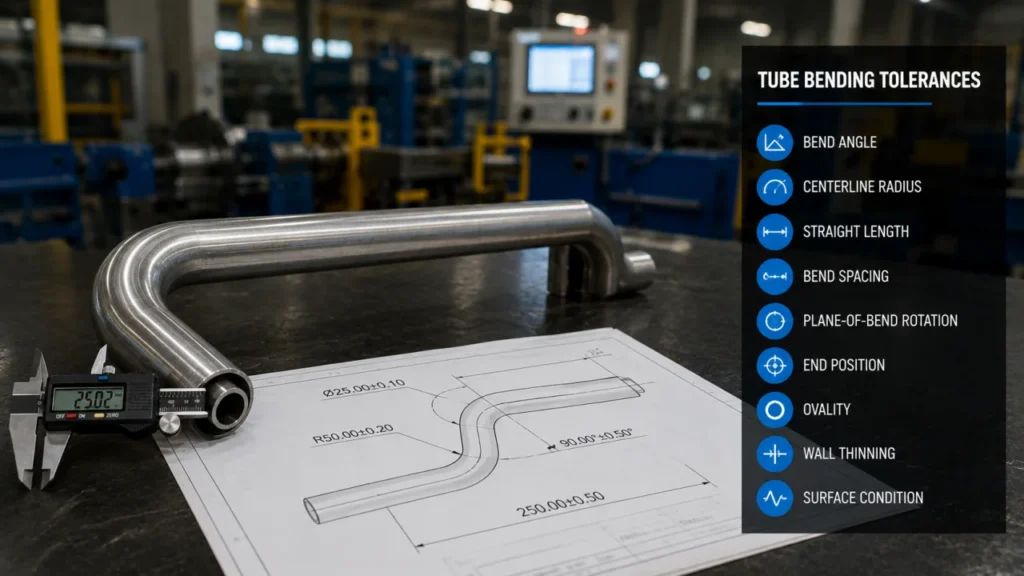
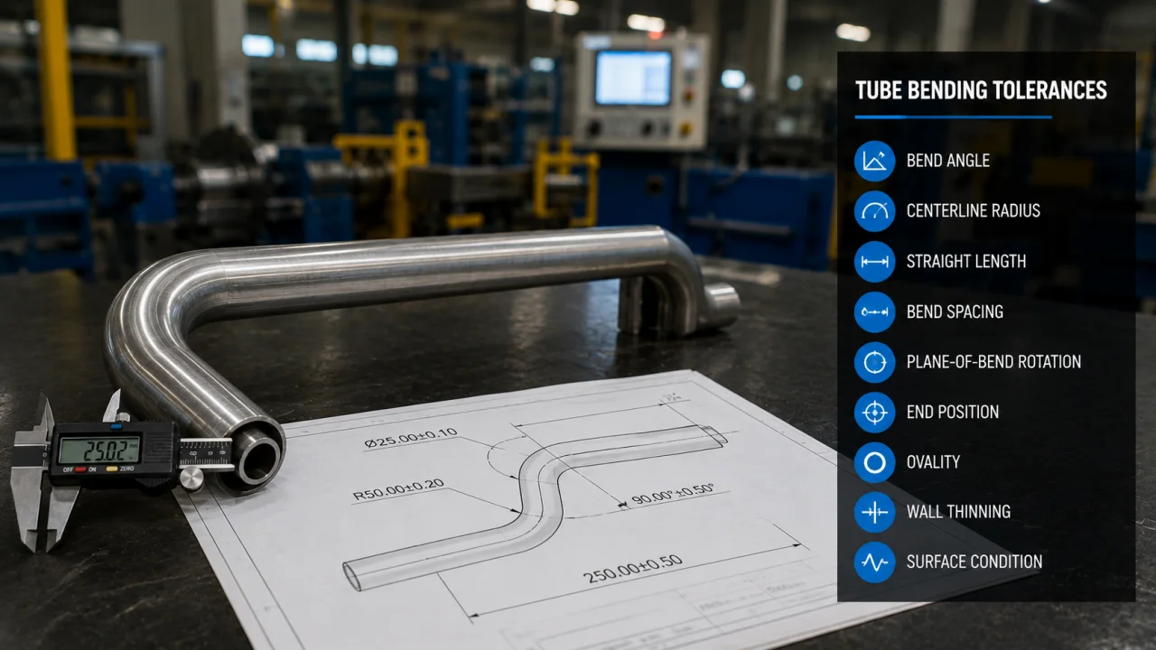
Tube bending tolerances define the permitted difference between your finished tube and the requirements on its drawing. Your specification may control bend angle, centerline radius, straight length, bend spacing, plane-of-bend rotation, end position, ovality, wall thinning, and surface condition.
Choose the controls from your part’s function. If you design a frame support, you may need accurate mating points. A fluid line may require round ends and controlled connector positions.
Machine Accuracy vs. Finished-Part Tolerance
Your machine builder may state accuracy for the bending, rotation, or feeding axis. Those values describe controlled machine movements. At the same time, your finished tube bending tolerances reflect material variation, tooling condition, springback, tube geometry, and the inspection setup.
Keep five terms separate during an RFQ:
- Machine-axis accuracy: the stated accuracy of a controlled axis.
- Programmed value: the bend, feed, or rotation value entered by the operator.
- First-piece result: the dimensions measured after setup and trial bending.
- Finished-part tolerance: the permitted deviation on the customer drawing.
- Batch repeatability: the process’s ability to hold the approved result during production.
Ask your supplier to review the drawing and test the material before confirming demanding tube bending tolerances.
Which Tolerances Should Be Specified on a Bent-Tube Drawing?
You should place tight tube bending tolerances on dimensions that control fit, sealing, welding, or interchangeability. General tolerances can cover noncritical dimensions and reduce unnecessary tooling or inspection work.
Bend Angle and Centerline Radius
The bend angle describes the direction change between straight sections. The centerline radius, or CLR, affects finished geometry, tooling selection, and section distortion.
Your drawing should also make the tangent points clear when they matter. If you measure from unclear edges or deformed areas, the customer and supplier may get different results. Before tooling starts, agree on the reference lines and inspection method for a tight angle requirement.
Straight Length, Bend-to-Bend Distance, and End Position
Your straight lengths and bend-to-bend distances determine where each bend starts. As a result, a feed error can shift later features and make you miss the endpoint target while individual angles pass inspection.
End position often provides a better functional control than a chain of intermediate dimensions. If your tube must connect two fixed ports, define the end location and orientation from stable datums. You can then loosen intermediate dimensions that do not affect assembly.
Plane-of-Bend Rotation
Multi-plane parts require the machine to rotate the tube between bends. A small rotation error changes later bend directions and can create a large endpoint error. For 3D parts, identify the bend planes or provide unambiguous coordinate data.
Ovality, Wall Thinning, and Surface Condition
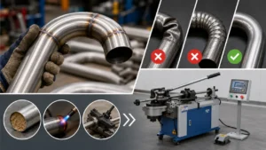
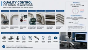
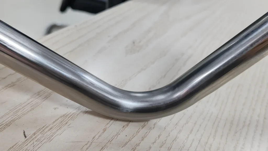
Dimensional tube bending tolerances do not cover all bend quality requirements. The outside wall stretches, the inside wall compresses, and the cross-section may become oval.
You should specify ovality, minimum wall thickness, wrinkling limits, or tool-mark requirements only where the application needs them. Use the applicable product code or customer specification for acceptance values.
| Drawing requirement | Why it matters | Common inspection approach |
|---|---|---|
| Bend angle | Controls direction and assembly fit | Angle gauge, fixture, or digital measurement |
| End position | Controls connection and mounting location | Fixture, CMM, measuring arm, or 3D system |
| Plane of bend | Controls multi-plane geometry | CMM or tube measuring system |
| CLR | Affects geometry and tooling | Profile comparison or coordinate measurement |
| Ovality | Affects flow, sealing, and appearance | Major and minor diameter measurement |
| Wall thinning | Affects strength and service performance | Wall-thickness measurement |
ASME Y14.5 and ISO 1101:2017 provide rules for communicating dimensional and geometric requirements. They do not establish one universal finished tolerance for bent tubes. Industry documents such as PFI ES-24 address specific pipe-bending applications, so you must check scope before using a listed value.
What Determines Achievable Tube Bending Tolerances?
Your production team controls tube bending tolerances through material management, suitable tooling, machine setup, program correction, and inspection. A weakness in one area can erase gains made elsewhere.
Material Grade and Batch Consistency
Springback changes with yield behavior, hardness, wall thickness, and material condition. You may see two tubes with the same nominal grade respond differently when their properties or dimensions vary within the purchasing specification. Stainless steel, aluminum, carbon steel, and copper also require different setup strategies.
Record the material and batch used for the approved sample. A change may require another trial bend.
Tube OD, Wall Thickness, and CLR
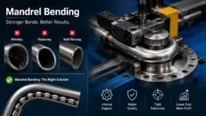
Tube outside diameter, wall thickness, and CLR shape the forming load and deformation risk. If you process a thin-wall tube or tight radius, you may need a mandrel, wiper die, controlled pressure-die movement, or a slower bend.
Diameter-to-wall and CLR-to-diameter ratios help engineers screen bending difficulty, but the production team still needs a trial with the specified material and tooling.
Tooling Selection and Setup
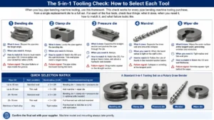
The bend die establishes the radius. The clamp and pressure dies control the tube, while a mandrel and wiper die support demanding bends.
During production, tool wear, poor groove fit, incorrect mandrel position, or unstable clamping can change tube bending tolerances. You should record approved positions and inspect contact surfaces during setup.
Machine Axes and Program Control
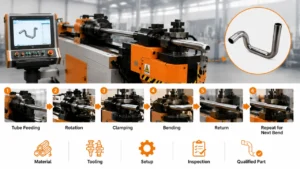
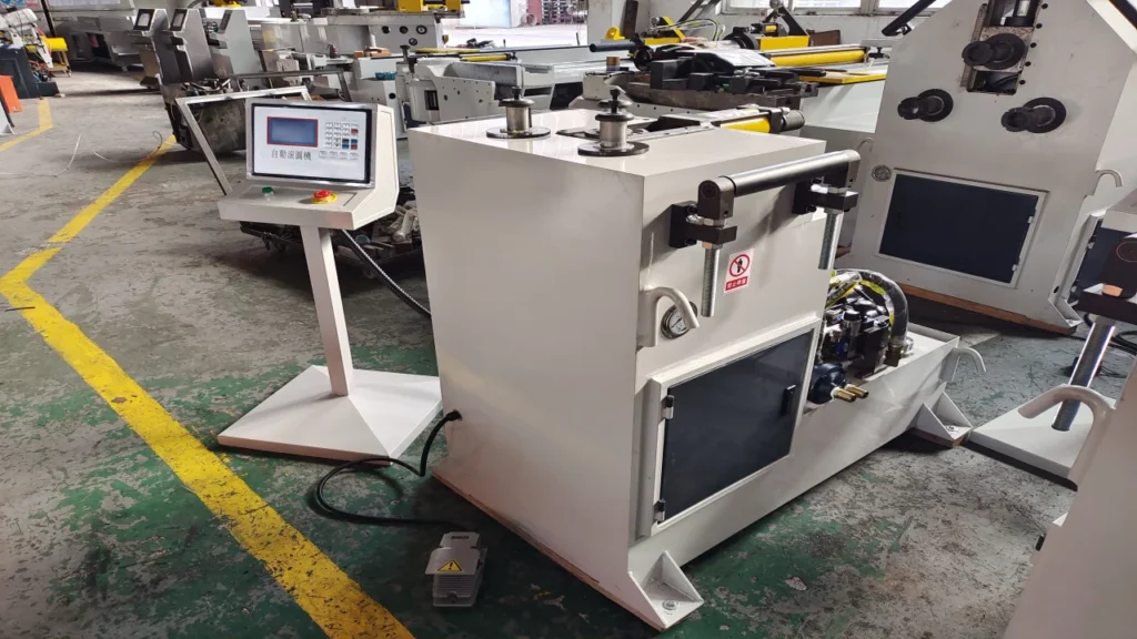
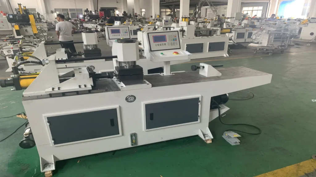
A CNC tube bender coordinates feeding, rotation, and bending. Your part geometry and output target determine whether you need more controlled axes.
For example, ZR’s DW38CNC-4A-2S specification lists working accuracy of ±0.1° for bending and rotation and ±0.1 mm for feeding. These figures describe specified machine work accuracy. They do not guarantee the same tube bending tolerances on each finished component. Use your drawing, material, tooling, and sample result to evaluate the complete process. ZR’s CNC pipe bending machine range includes configurations for different tube sizes and automation needs.
Springback and Multi-Bend Error Accumulation
The tube recovers after the bending force releases. CNC controls can apply compensation based on the measured sample, but material or geometry changes can alter the required correction.
Multi-bend parts add another problem. Feed, rotation, and angle deviations combine across the sequence. If you check only the last endpoint, you cannot identify which operation caused the error. Compare each YBC step with the measured geometry before changing the program.
A 7-Step Workflow for Controlling Tube Bending Tolerances
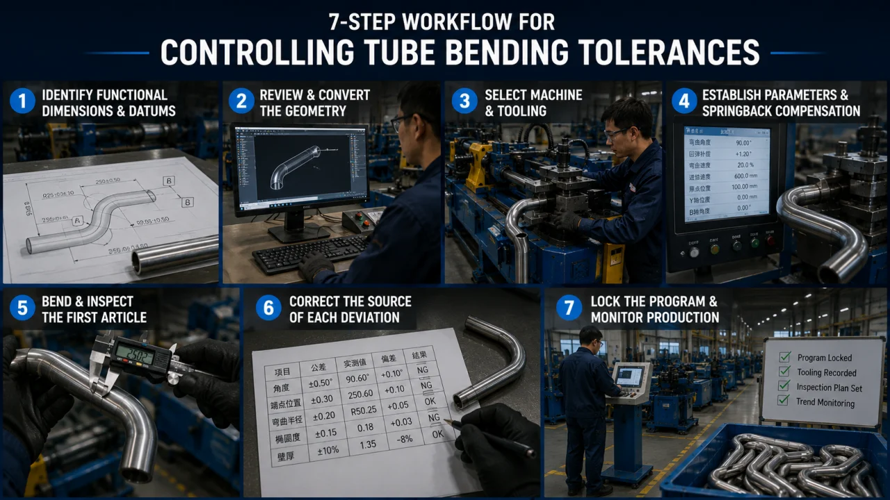
A controlled workflow connects your drawing to the approved production part. The following seven steps give your engineering and purchasing teams a common review process.
Step 1: Identify Functional Dimensions and Datums
Mark connection points, mounting surfaces, weld locations, and clearance zones. Select datums that let you and the supplier hold and measure the tube in the same way.
Assign tight tube bending tolerances to features that control function. Use appropriate general tolerances for the remaining dimensions. Confirm whether the customer will inspect individual bend values, final endpoints, a profile, or a combination of these controls.
Step 2: Review the Drawing and Convert the Geometry
You should provide a dimensioned 2D drawing and a 3D model for complex parts. Your engineering team can convert XYZ coordinates into YBC feed, rotation, and bend data, then check clamping, bend spacing, interference, and secondary operations.
Step 3: Select the Machine and Tooling
You should match the machine and tooling to the material, tube size, CLR, bend sequence, and required output.
High output may justify automatic handling. Complex multi-plane parts benefit from CNC feeding and rotation.
Step 4: Establish Initial Parameters and Springback Compensation
Program the feed, rotation, bend angle, speed, and tooling actions. You should run the specified tube and measure it before approving a compensation value.
ZR CNC control documentation includes a springback compensation setting and program storage. Operators can retain an approved job program and restrict access to production data. These functions support process control, while sample inspection confirms the finished result.
Step 5: Bend and Inspect the First Article
You should place the sample in the agreed inspection setup. Check functional dimensions, angle, spacing, rotation, end position, ovality, and surface condition where specified.
You should record nominal values, measured results, and deviations. A pass or fail note without measurement data gives the setup technician little information for correction.
Step 6: Correct the Source of Each Deviation
You should match each error to its control. Adjust compensation for a stable angle error, feed data for a location error, and rotation data for a plane error.
You cannot fix all problems through program edits. Ovality or wrinkles may require a tooling-position change, more support, or a different process. Random variation may point to tube inconsistency, clamping, lubrication, or wear.
Step 7: Lock the Program and Monitor Production
You should save the approved program, record tooling positions, restrict edits, and set inspection frequency from part risk and measured stability.
You should recheck tube bending tolerances after a material batch change, tooling service, machine adjustment, or unexpected trend. Early checks keep a small shift from becoming a full batch of rejected parts.
How Should You Inspect Bent Tubes?
Choose an inspection method that matches your geometry, tube bending tolerances, and production volume.
Manual Measurement
You can inspect simple parts with angle gauges, calipers, height gauges, and surface plates. These tools suit development checks and low-volume components with accessible features. Your technique and part placement can limit repeatability on complex 3D tubes.
Dedicated Checking Fixtures
A fixture locates the tube from defined datums and checks features. You can use it for fast production decisions, but it adds design and manufacturing cost and checks only the features built into it.
CMM, Measuring Arms, and 3D Systems
Coordinate measuring machines, portable arms, and tube measurement systems can compare complex geometry with CAD data. They support multi-plane inspection and first-article reports. Both parties still need to agree on datums, probe points, and reporting rules.
Agree on the Measurement Method Before Production
You should write the datum scheme, clamping condition, measurement points, equipment, sampling frequency, and acceptance record into the quality plan. This agreement prevents one party from measuring a relaxed tube while the other constrains it in a fixture.
Why Do Tube Bending Tolerances Drift During Production?
You need to track production patterns rather than correct each failed part in isolation.
| Observed deviation | Possible cause | First check |
|---|---|---|
| Bend angle changes over time | Material response or tooling wear | Compare material batch and die condition |
| Final endpoint misses its location | Accumulated feed, rotation, or angle deviation | Inspect each YBC step |
| Bend angle passes but the part does not fit | Datum, rotation, or positional error | Verify fixture alignment and end coordinates |
| Ovality increases | Loss of tooling support or lubrication change | Check mandrel, pressure die, and lubrication |
| Results vary without a clear trend | Tube variation or unstable clamping | Measure stock and inspect clamp contact |
Use measured trends to choose the correction. Repeated angle drift may call for compensation or material review. Random scatter requires a check of the tube, clamp, machine condition, and measurement process.
How Tight Tolerances Affect Machine Configuration and Cost
You should apply tight tube bending tolerances at interfaces that control assembly, sealing, welding, clearance, or part interchangeability. You can often relax intermediate straight lengths or nonfunctional angles without changing product performance.
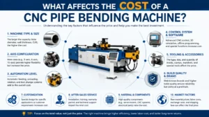
Tighter requirements can increase trial bends, inspection time, and scrap exposure. Complex profiles may need a dedicated fixture or 3D inspection.
You should match automation to the job. CNC feeding and rotation support repeatable multi-bend production. Automatic loading can reduce handling variation at high output. Low-volume parts with frequent changes may gain little from a larger package. Ask the supplier to review your drawing and daily output before recommending a configuration.
Application Example: Q235 Electric-Vehicle Frame Support
An electric-vehicle frame support project used Q235 tube with a 25 mm OD and 2 mm wall thickness. The drawing specified an approximate cut length of 370 mm, a 60 mm CLR, a 40° bend, and a required bend-angle tolerance of ±0.1°. Both ends needed notching to fit a 35 mm mating tube. The production target was 800 parts in an eight-hour day.
The proposed sequence was cutting, bending, and double-sided notching. Bending first kept the tube ends available for handling. A CH60NC matched the specified notching operation.
The ±0.1° value represents the customer’s drawing requirement. You must confirm it with the specified Q235 tube, production tooling, trial bends, and an agreed inspection method. Machine work accuracy alone does not prove the finished result. You should also check whether angle tolerance controls assembly or whether the drawing needs an endpoint or profile requirement.
You should submit the complete component rather than ask whether a machine can hold one isolated number. Your daily target also affects loading, handling, inspection, and the automation required to maintain tube bending tolerances throughout the shift.
What Should You Send to a Tube Bender Supplier?
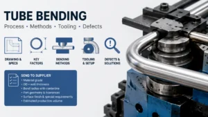
Your supplier can assess tube bending tolerances faster when the RFQ contains:
- A dimensioned 2D drawing and a 3D model for complex geometry
- Material grade, tube OD, and wall thickness
- CLR, bend angles, bend sequence, and number of bends
- Functional dimensions, datums, and tolerance values
- End forming, notching, punching, or welding requirements
- Daily or annual production quantity
- Surface requirements and permitted tool marks
- Inspection method, sampling plan, and required records
ZR can review these inputs to recommend a process sequence, machine configuration, tooling approach, and trial plan. Send your drawing and production requirements for a project-specific assessment.
Frequently Asked Questions About Tube Bending Tolerances
What Is a Typical Tube Bending Tolerance?
No single value suits all bent tubes. Material, OD, wall thickness, CLR, number of bends, tooling, and inspection method affect the achievable result. Specify the dimensions that control function, then ask the supplier to confirm them through drawing review and sample testing.
Is There a Universal Tube Bending Tolerance Standard?
Drawing standards define how engineers communicate dimensional and geometric requirements. Some industry documents also give requirements for specific types of pipe bends. Their scope may not cover automotive frames, furniture, or small industrial tubes. The drawing, customer specification, and applicable product code should define acceptance.
Does CNC Machine Accuracy Equal Finished-Tube Tolerance?
No. CNC axis accuracy describes machine movement. Finished tube bending tolerances include material response, springback, tooling, clamping, program data, and measurement variation. Confirm the complete part with the specified tube and a documented first-article inspection.
How Do You Measure Tube Bend Angle Tolerance?
Measure from the reference lines, tangents, or datums defined on the drawing. Simple parts may use an angle gauge or fixture. Multi-bend parts may require a CMM, measuring arm, or tube measurement system to evaluate angle and position together.
How Do You Calculate Tube Bending Tolerance?
Engineers do not derive finished tolerance from one bend formula. They allocate tolerance from product function, assembly clearance, accumulated variation, and proven process capability. Bend calculations can establish geometry and developed length, while trials and inspection establish manufacturing capability.
Why Can Tube Bending Tolerances Change Between Material Batches?
Different batches can vary in yield behavior, hardness, OD, or wall thickness within the material specification. Those changes affect springback and deformation. Record the approved material batch and inspect another trial part when a new batch produces a measurable shift.
Get a Drawing-Based Tube Bending Recommendation
Reliable tube bending tolerances start with clear functional requirements and continue through tooling, CNC programming, trial bending, inspection, and production monitoring. Send ZR your drawing, tube specification, critical tolerances, and output target. The engineering team can review the process and recommend a suitable machine and tooling configuration.