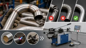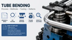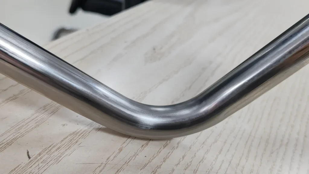
A bent tube can reach the specified angle and still fail inspection because its cross-section has become too oval. Before you increase pressure or change a tool, confirm how the drawing defines tube ovality, where the inspector measures it, and which diameter the formula uses. This guide explains how to calculate and measure the result, trace the likely causes, adjust tooling and process settings in a controlled order, and verify a machine configuration before production.
What Is Tube Ovality, and Why Does It Matter After Bending?
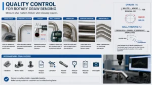
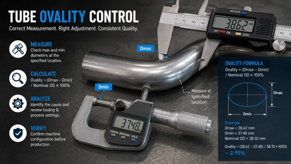
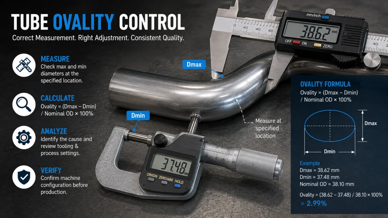
Tube ovality describes how far a round tube cross-section has moved away from its intended circular shape. Inspectors often identify the largest outside diameter,Dmax, and the smallest outside diameter,Dmin, at the same cross-section. The Steel Tube Institute handbook defines ovality as the difference between the maximum and minimum diameters measured at one section of round tube.
Outside-diameter tolerance compares a reading with the ordered size. Ovality compares directions at one section. A tube can meet its average diameter requirement yet remain too distorted for its application.
Ovality, flattening, wall thinning, and wrinkling
Several bend defects can appear together, but each one describes a different condition.
| Condition | What you inspect | Common location |
|---|---|---|
| Tube ovality | Difference between the largest and smallest diameters | Across a specified bend cross-section |
| Flattening | Loss of section depth or a visibly flattened profile | Often through the bend arc |
| Wall thinning | Reduction in wall thickness | Usually at the outside radius |
| Wrinkling | Waves caused by local wall instability | Usually at the inside radius |
A diameter measurement cannot replace a wall-thickness check, and a wrinkle-free surface does not prove that the cross-section meets the ovality requirement.
Why the finished shape affects the part
Excessive tube ovality can interfere with a fitting, clamp, weld preparation, seal, or mating component. In a fluid path, cross-sectional distortion can also change the available flow area. For visible frames or furniture, the same distortion may create an appearance problem even when the part still assembles.
The drawing and final use set the allowable result. Structural members, hydraulic lines, exhaust tubes, and furniture components do not share one acceptance limit.
How Do You Calculate and Measure Tube Ovality?
You need three items before calculating tube ovality: Dmax, Dmin, and the reference diameter required by the governing document. Two formulas appear in technical references, so state the denominator.
Formula based on nominal outside diameter
Some specifications use the nominal tube outside diameter:
Tube ovality (%) = (Dmax - Dmin) / Dnom × 100
An NFC technical specification uses this formula for its specified U-bend tubes. Its 5% limit belongs to that project and is not a general limit for all bent components.
Formula based on mean diameter
Other references use the mean of the two measured diameters:
Dmean = (Dmax + Dmin) / 2
Tube ovality (%) = (Dmax - Dmin) / Dmean × 100
An IIETA research paper uses the mean-diameter convention in its study of bent copper tube. The paper supports the formula, but its experiment does not define the acceptance requirement for another material, bending method, or machine.
Illustrative calculation
Assume a nominal 25.00 mm tube measures 25.40 mm at its widest direction and 24.60 mm at 90 degrees to that direction.
Dmax - Dmin = 25.40 - 24.60 = 0.80 mm- Nominal-diameter result:
0.80 / 25.00 × 100 = 3.20% - Mean diameter:
(25.40 + 24.60) / 2 = 25.00 mm - Mean-diameter result:
0.80 / 25.00 × 100 = 3.20%
Both formulas match in this balanced example. They can differ when the mean measured diameter differs from the nominal diameter. These values demonstrate the calculation and do not represent a ZR test or acceptance limit.
A repeatable measurement procedure
Use the same method for the first sample, production checks, and final acceptance.
- Read the drawing or inspection plan. Confirm the formula, limit, cross-section, and sampling requirement.
- Measure the incoming tube. Record its initial
Dmax,Dmin, wall thickness, material batch, and surface condition. - Mark the specified section on the bend. If the document does not state a position, agree on one before approving the sample.
- Rotate the measuring direction around the section to find the largest and smallest outside diameters.
- Record the instrument, sample number, section position, values, formula, and calculated result.
- Compare samples only when the team used the same measurement convention.
A caliper or outside micrometer supports two-point checks when the agreed method permits it. A roundness instrument evaluates more of the contour. The ASME B89.3.1 description covers profile-based evaluation but does not set requirements for a specific product. A two-point tube ovality result is not a complete roundness-profile analysis.
Why Does Tube Ovality Increase During Bending?
During bending, the outside wall stretches while the inside wall compresses. The changing stress state and radial forces distort the cross-section as the tube moves through the bend. The final shape depends on the tube, bend geometry, tooling, and machine setup.
Bend radius and wall thickness
A tighter centerline radius places greater forming demands on the tube. A thinner wall gives the cross-section less resistance to distortion. The IIETA study reports more pronounced ovalization with low wall thickness and small bend radius under its test conditions.
Ratios such as CLR/OD and OD/wall thickness help engineers compare bend severity. They do not create a universal pass/fail rule because material, tooling, angle, and quality requirements still affect the result.
Incoming tube and material variation
Measure the incoming material before blaming the bender. The tube may already have ovality from manufacturing, storage, handling, or a previous operation. Actual wall thickness can also vary within the purchased tolerance.
Record the material grade and condition for each trial. For welded tube, record seam orientation when the project treats it as a controlled variable.
Tooling fit, wear, and slippage
A tool groove must match the tube closely enough to support and control it without creating unwanted marks or drag. Worn tools, an incorrect groove, poor clamping, or tube slippage can change the way material enters the bend.
Mark the tube near the clamp before a trial. Movement between the mark and the tooling gives you evidence of slippage. Inspect wear and contact patterns before increasing clamp pressure.
Pressure, speed, and lubrication
Pressure-die force, assist movement, speed, and lubrication affect material flow. More pressure does not guarantee lower tube ovality and may hide a tooling-position problem.
Change one controlled variable at a time. Record the old setting, new setting, material batch, and measured outcome. Without that record, a better sample does not give you a repeatable production process.
How Can Tooling Control Tube Ovality?
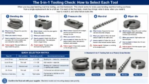
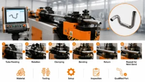
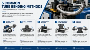
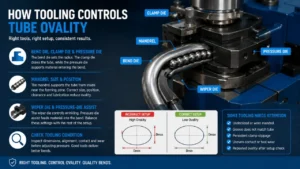
Rotary draw bending uses a coordinated tool set. Each tool has a specific job, and one incorrect position can mask another problem.
Bend die, clamp die, and pressure die
The bend die establishes the radius. The clamp die draws the tube with it, while the pressure die supports material entering the bend.
Check tool dimensions, alignment, contact, and wear before making large pressure changes. The OMNI-X bending-defects guide identifies OD, centerline radius, wall thickness, material, tooling, and setup as factors in bend deformation.
Mandrel size and position
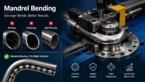
A mandrel supports the tube from inside near the forming zone. Thin-wall or tight-radius work may require more internal support than an open draw bend. The correct choice depends on the actual job.
A mandrel alone does not solve tube ovality. Nose diameter, clearance, position, lubrication, and extraction timing influence performance. The Bend Tooling troubleshooting guide explains that an undersized nose or shallow placement can contribute to excessive ovality and flattening.
Move the mandrel through a controlled setup procedure. Excessive advancement can create marks, drag, or removal problems.
Wiper die and pressure-die assist
The wiper die supports the inside wall near tangency and primarily helps control wrinkling. It does not replace an incorrectly sized mandrel. Pressure-die assist or boost can feed material toward the bend in suitable machine and tooling configurations. The operator must balance that movement with the rest of the setup.
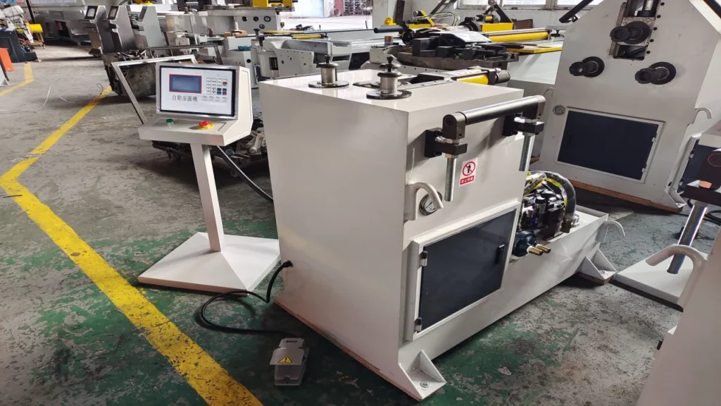
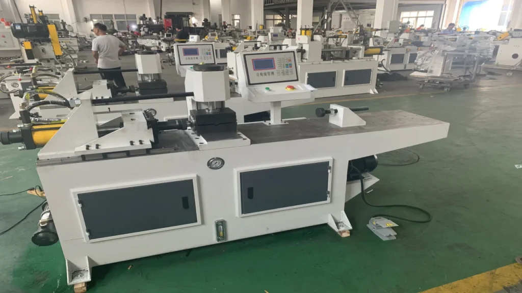
ZR’s CNC pipe bending machine range lists tooling scope, including mandrel, wiper, and boost options, as a configuration factor. Treat these as project-specific options. The finished result still depends on the tube, tool design, settings, and agreed inspection method.
Signs that the tooling needs attention
Review the tooling rather than adding more pressure when you find:
- an undersized or worn mandrel;
- a groove that does not match the actual tube;
- persistent clamp slippage;
- visible uneven contact or tool wear;
- repeated ovality after the team has checked the documented setup.
A new parameter cannot repair a damaged tool or add missing internal support.
A Six-Step Method to Diagnose Excessive Tube Ovality
The following sequence keeps tube ovality troubleshooting measurable and prevents simultaneous changes from hiding the cause.
1. Define the requirement
Write down the formula, allowable value, inspection section, measuring instrument, and sample frequency. Confirm whether the customer applies the requirement to incoming tube, the finished bend, or both.
2. Measure incoming material
Record the starting cross-section and actual wall thickness. Link each measurement to a material heat, batch, or supplier lot when that information is available. A poor starting condition reduces the process window.
3. Check bend severity and part geometry
Review OD, wall thickness, CLR, bend angle, tangent lengths, and nearby bends. Confirm that the selected bending process and tool package can reach the geometry without interference.
4. Inspect tooling and setup
Check the bend-die groove, clamp engagement, pressure-die position, mandrel size and depth, wiper condition, lubrication, and tube slippage. Use marks and measurements instead of relying on visual judgment alone.
5. Adjust one variable at a time
Choose the variable that corresponds to the observed symptom. Make a bounded adjustment, run a labeled sample, and measure it with the agreed method. Keep other inputs constant where production conditions allow.
6. Verify and lock the process
One acceptable sample does not prove repeatability. Run the agreed quantity, record each tube ovality result, and retain the program and tooling setup. Recheck after material, tooling, or maintenance changes.
| Symptom | First check | Possible action | Verification |
|---|---|---|---|
| High incoming ovality | Raw tube at several sections | Segregate material or review supplier specification | Repeat incoming measurements |
| Elliptical bend with poor internal support | Mandrel size and position | Correct the mandrel configuration within setup guidance | Measure the same bend section |
| Ovality varies between samples | Slippage, material batch, and setup repeatability | Correct the identified source and hold other variables constant | Compare a labeled sample series |
| More pressure makes flattening worse | Pressure-die drag and tool alignment | Restore the setup sequence before adding force | Recheck ovality and tool marks |
| Result changes after long production | Tool wear, lubrication, and material variation | Inspect and document the changed condition | Repeat the approved inspection plan |
What Is an Acceptable Tube Ovality?
No single percentage applies to every bent tube. The designer or customer must connect the requirement to the part’s function, material, geometry, and inspection convention.
The Steel Tube Institute discussion of curved HSS distortion explains that acceptable tolerances depend on structural and architectural requirements. Its examples concern HSS work and should not become default limits for a precision tube, pressure line, exhaust component, or furniture frame.
Resolve these questions before production:
- Which formula and reference diameter apply?
- At which cross-section will the inspector measure?
- Which instrument and contact method will the team use?
- How many parts and sections will the team inspect?
- Does the drawing control incoming material, the finished bend, or both?
- Who decides whether to accept a borderline result?
Put the answers in the drawing, inspection plan, purchase specification, or approved sample record. That agreement prevents two parties from calculating different tube ovality percentages from the same part.
How Should You Specify a Tube Bending Machine for Ovality Control?
Ask the supplier to review the part, tooling, process controls, and validation method together. Machine capacity alone cannot define the finished cross-section.
Information to send the supplier
Provide:
- the finished drawing and application;
- material grade and condition;
- tube OD and actual wall-thickness range;
- CLR, bend angle, and tangent lengths;
- all bends, rotations, holes, and end features;
- tube ovality formula, limit, and inspection section;
- surface requirements;
- expected batch size or daily output;
- actual tube samples when material variation affects the project.
This information helps the supplier select machine capacity, axis configuration, tooling, internal support, and production method. It also gives both parties a basis for sample acceptance.
Compare the complete configuration
Compare quotations by machine, bend tooling, mandrel and wiper requirements, assist options, program control, changeover method, inspection scope, and sample test. A lower machine price may exclude tooling or validation work needed for the part.
ZR’s DW-series source materials list features such as servo-controlled motion on applicable models, slow bending, slow mandrel extraction, and program storage. These functions give the operator ways to control and reproduce the process. They do not guarantee a specified tube ovality without matched tooling and verified material.
Validate the process with the actual tube
ZR’s published tube bending sample service asks customers to provide drawings and tube information. The page states that ZR can test customer material, adjust bending speed, clamping force, mandrel position, pressure-die movement, and compensation, then inspect the sample and record key dimensions. The same page includes ovality among the sample checks.
Use the sample approval to confirm the formula, measurement location, tooling, program, and acceptable result. Repeat the check under agreed production conditions before treating the setup as ready for volume work.
Send your drawing, material, tube OD, wall thickness, CLR, bend angle, ovality requirement, inspection method, and production target for a tooling and machine configuration review. Contact ZR and upload your drawing.
Frequently Asked Questions About Tube Ovality
What is tube ovality?
Tube ovality is the difference between the largest and smallest diameters measured at the same tube cross-section. You can express the difference in millimetres or as a percentage. The percentage formula must identify its reference diameter, such as nominal OD or mean measured diameter.
How is tube ovality calculated?
Measure Dmax and Dmin at one specified section. Then calculate (Dmax - Dmin) / reference diameter × 100. Use the reference diameter required by the drawing, customer specification, inspection plan, or applicable standard. Do not compare results that use different denominators.
Where should ovality be measured on a bent tube?
Use the cross-section stated on the drawing or inspection plan. If no location appears, the customer and supplier should agree on the position before sample approval. Record the position so inspectors can repeat the measurement during production.
Does a mandrel eliminate tube ovality?
No. A correctly sized and positioned mandrel can support the cross-section and reduce deformation. The result also depends on the tube material, wall thickness, bend radius, tooling fit, lubrication, and machine setup. A mandrel cannot provide a universal result by itself.
What is the difference between tube ovality and flattening?
Ovality compares the largest and smallest diameters at one cross-section. Flattening describes a loss of section depth or a visibly flattened profile. The terms often overlap in workshop use, so the inspection document should define the measured characteristic and formula.
What information does a machine supplier need to control ovality?
Send the drawing, material grade, OD, wall thickness, CLR, bend angle, tangent lengths, surface requirements, production target, and the required tube ovality formula and inspection position. Actual tube samples help when material condition or dimensional variation may affect the bend.
Control the Measurement Before You Control the Bend
Define the acceptance method, measure the incoming tube, check tooling in sequence, and change one process variable at a time. A documented sample test then shows whether the selected machine and tooling configuration can meet the requirement with the supplied material.