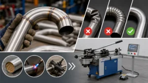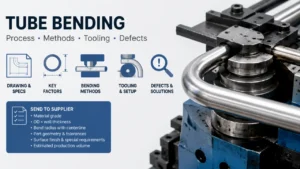
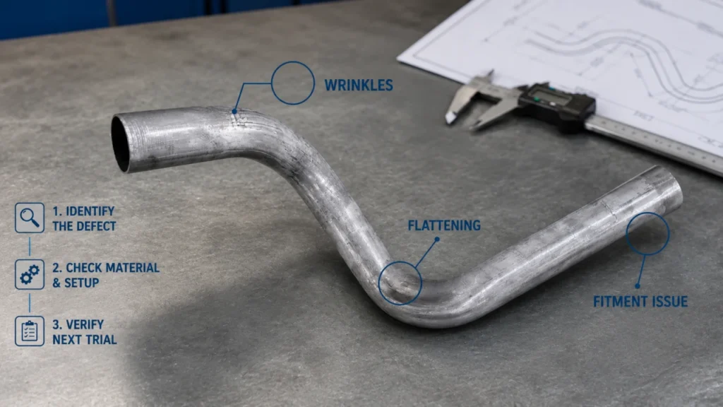
A wrinkled bend, a flattened section, or a part that will not fit its fixture can leave you unsure what to change. Increasing pressure or replacing tooling without a diagnosis may waste another batch of tube. To investigate tube bending defects, start with the visible problem, check the material and setup, then verify the next trial against your drawing. This guide focuses on metal tubing, with tooling and setup advice directed at rotary draw bending rather than roll bending or plastic-tube forming.
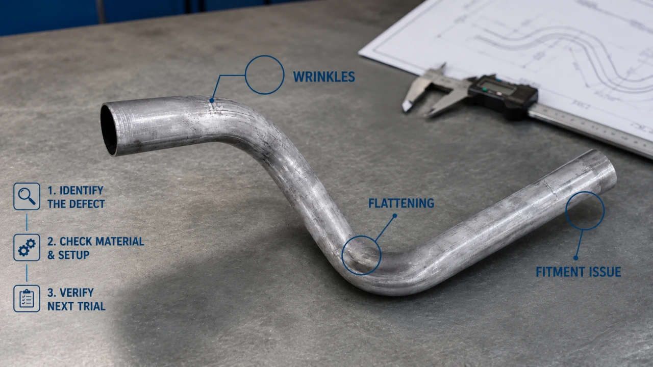
Identify Tube Bending Defects Before Changing Settings
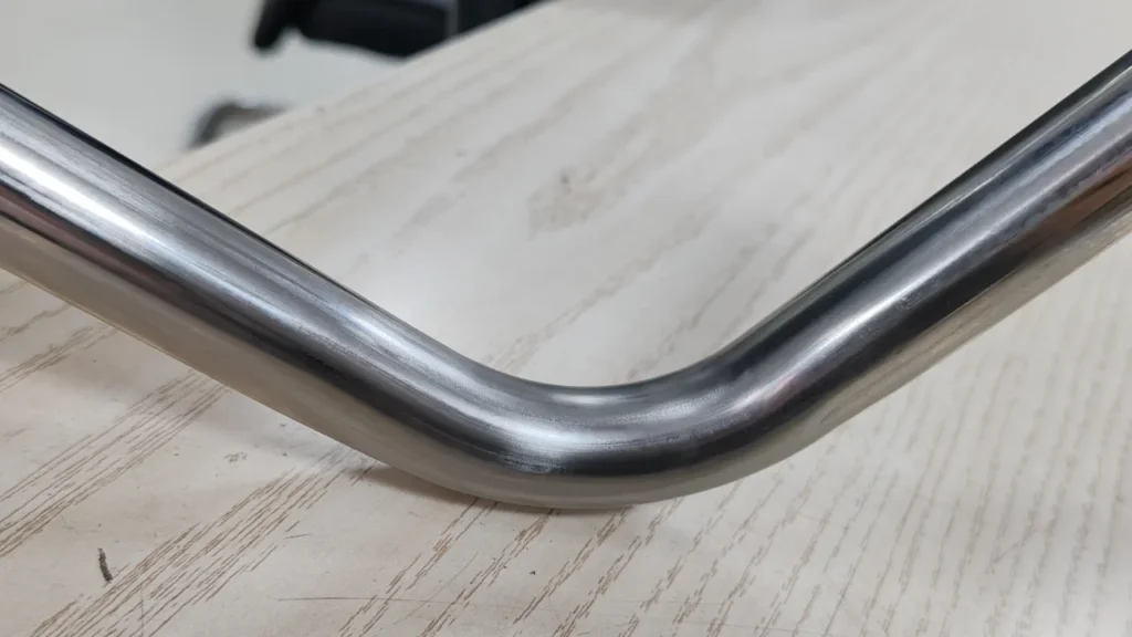
Record where the problem appears and whether it affects one bend, one part, or a production batch. A close-up helps identify a surface feature; an overall photograph shows its position on the component. Neither establishes the cause on its own.
Use this table to document tube bending defects before changing the setup.
| Observation | Where to look | Information to collect |
|---|---|---|
| Wrinkles or folds | Inside bend radius and bend transitions | Extent of wrinkling, tooling identification, setup record |
| Flattening or local collapse | Cross-section along the bend | Incoming diameter, formed-section measurements, support configuration |
| Suspected excessive thinning | Outer bend wall | Starting wall thickness, remaining thickness, drawing requirement |
| Crack or split | Bend surface and any visible seam | Location, material identification, condition before bending |
| Scratches or tool marks | Bend, gripping area, and straight sections | Mark direction, incoming surface, contacting tool |
| Suspected slippage | Gripping area and bend location | Grip condition, clamping length, dimensional results |
| Angle or orientation error | Released bend and complete component | Target dimensions, measured geometry, program revision |
Some changes occur as part of forming. Your acceptance criteria determine whether the resulting geometry or wall thickness is acceptable. Treat a suspected crack as a separate quality concern: isolate the affected parts for assessment rather than continuing on the assumption that the surface can be repaired.
Tube Bending Defects by Symptom and Location
Wrinkling on the Inside of the Bend
Wrinkles appear as waves or folds on the inside radius. Note whether they extend along the bend or occur near its end. That distinction gives your tooling supplier more useful information than a general report that the tube is wrinkling.
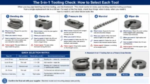
Where those tools are part of your setup, review mandrel fit and position, wiper condition, and pressure-die setup against the approved tooling instructions. These items work together; changing one may alter another symptom. OMNI-X’s troubleshooting chart distinguishes several wrinkle patterns and associated checks.
To prevent recurring tube bending defects, preserve the validated setup and inspect the tooling before a new run. After an adjustment, check the whole bend, including its cross-section and surface. Removing a visible wrinkle does not prove the rest of the part meets the drawing.
Flattening, Ovality, and Local Collapse
An oval section has lost some of its original roundness. Local collapse involves a concentrated inward deformation. Record its shape and extent. Use consistent descriptions when reporting these tube bending defects.
Check actual tube size, wall thickness, tooling match, and the support arrangement. Compare the incoming section with the bent section so you can separate stock variation from deformation introduced during forming.
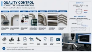
Agree how to calculate ovality and where to measure it. Different denominators or measurement locations can produce different reported percentages. Use the method required by your drawing or agreed specification; do not select an acceptance limit from an unrelated application.
Excessive Wall Thinning
The outer wall stretches during bending. The inspection question is whether enough wall remains for the component’s requirements. Bend Tooling defines minimum wall thickness as a finished-part requirement that controls allowable thinning.
Measure starting material as well as the formed region. A nominal stock thickness alone may not establish the actual change. Record the measurement location and method so another inspector can repeat the check.
Preventing tube bending defects associated with thinning requires a review of geometry, material flow, tooling, and applicable assist functions. Ask your supplier to evaluate those conditions together. Adding a mandrel does not establish a guaranteed remaining thickness, and a smooth outside surface does not establish wall thickness.
Cracking or Splitting
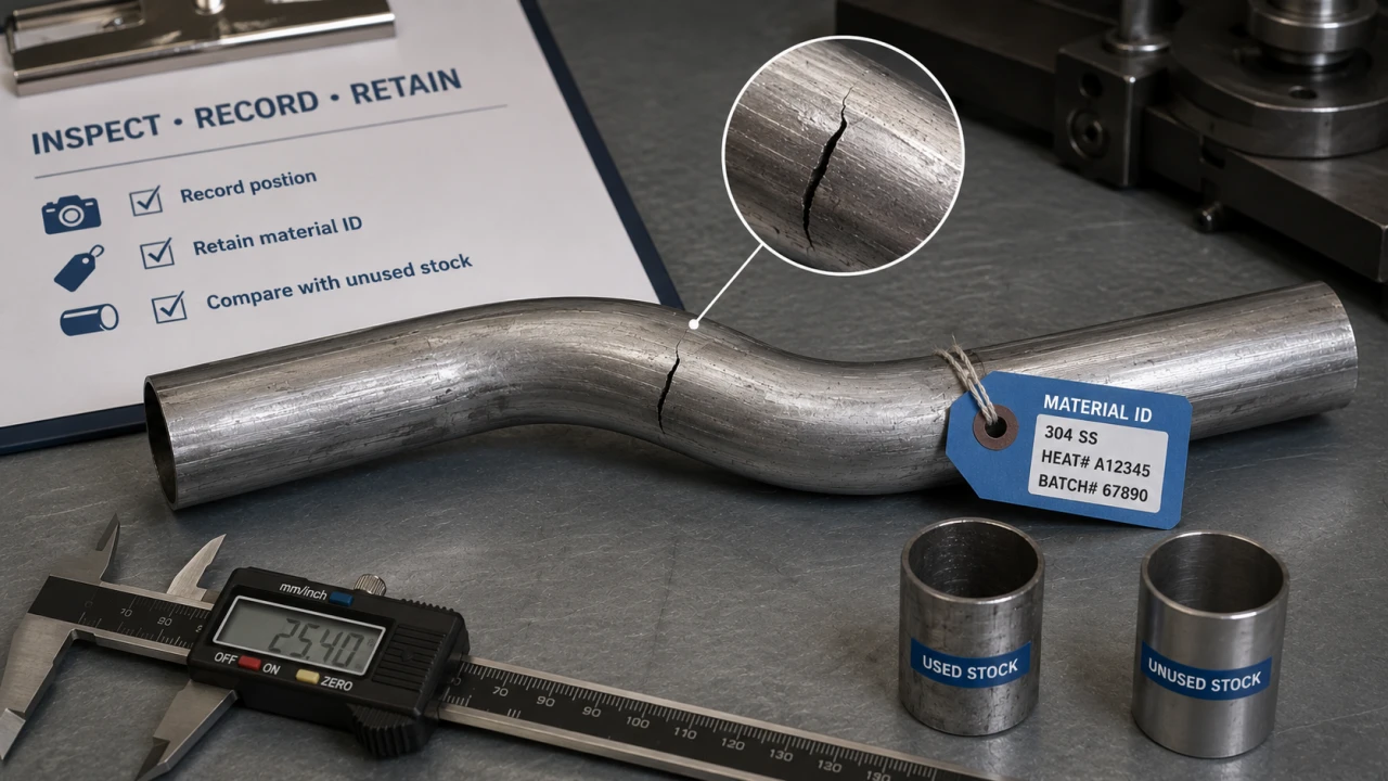
A crack requires more than a cosmetic correction. Record its position before handling or further processing obscures the evidence. Retain the material identification and compare the affected area with unused stock from the same batch.
Review material grade and condition, the forming demand, and tooling drag. The Tools For Bending technical manual discusses material elongation and how drag can stretch a tube wall toward rupture. These factors help investigate tube bending defects; they do not prove the cause of a particular crack.
Have qualified engineering or quality personnel determine the required assessment and disposition. Do not grind away the indication and assume that the component’s strength or suitability has been restored.
Scratches, Galling, and Tool Marks
Before classifying surface marks as tube bending defects, establish whether they existed before bending. Then compare their location with the areas that contact the clamp, pressure die, wiper, or internal support.
Inspect for contamination, damaged contact surfaces, alignment problems, and signs of material transfer. Review lubricant suitability and application against the tooling instructions. AMPCO’s discussion of bending problems identifies tool-material selection and galling as relevant surface-quality concerns.
Your customer’s requirements determine whether a mark is acceptable. Check specified depth or other surface criteria even for concealed components; visibility alone does not determine acceptance.
Tube Slippage During Bending
Slippage is a process problem that can accompany tube bending defects such as unacceptable surface marks or incorrect bend placement. A visible line in the gripping area is a clue to investigate, not a complete diagnosis.
Check available gripping length, tool fit, contact condition, and the relationship between clamping and forming resistance. Avoid increasing clamp force before understanding why the tube moved.
The Bend Tooling setup guide explains that excessive drag can contribute to slippage. After corrective work, verify grip performance alongside surface condition and finished dimensions. Check whether the revised grip leaves marks that exceed your surface requirements.
Angle Errors and Misaligned Bends
Measure the component after releasing the forming load. A bend that opens after release needs a different investigation from a bend located at the wrong distance along the tube.
For a multi-bend part, record bend angle, straight lengths, and orientation as separate results. For dimensional tube bending defects, review the drawing interpretation and program revision before changing compensation. Otherwise, you risk adjusting an angle to disguise a positioning or measurement problem.
Use repeat trials to establish whether the deviation is consistent. Save validated compensation with its material and tooling context. Do not assume that a setting remains correct after a material or setup change.
Troubleshoot Tube Bending Defects in a Controlled Sequence
Record the Defect and Check the Incoming Tube
Keep reference samples or photographs of tube bending defects before making changes. Note the part number, drawing revision, material batch, and point in the run when the problem appeared.
Check the incoming tube against the specified grade, size, wall thickness, and surface condition. Record differences rather than assigning blame to the material supplier or operator without evidence.
For example, if the first rejected part follows a stock-batch change, compare the two batches while preserving the setup record. Record the comparison and original settings.
Check Tool Fit, Condition, and Setup
Compare installed tooling with the approved tool list. Inspect its condition and confirm that the setup matches the instructions for the component.
Follow the machine manual and site safety procedures. Qualified personnel must stop and isolate equipment as required before entering hazardous areas or inspecting tooling. Do not reach into a moving machine to locate a mark or observe contact.
Separate a documented setup correction from a proposed redesign. If the job requires a different support arrangement, ask the tooling supplier to review it rather than improvising an unsupported configuration.
Make Documented Trials and Check for New Problems
Record the original settings before the trial. Where practical, change one factor at a time so you can connect the adjustment with the result. Coordinated changes may require supplier guidance.
Log trials for tube bending defects using consistent fields: trial identification, material batch, change made, measured outcome, and any new problem. Include an unchanged reference condition when it helps your investigation.
Use the improved sample to decide what to verify next. Define the further checks needed before restarting an affected run or accepting a new setup.
Verify the Part Against the Drawing
Check Released Geometry and Cross-Section
Check angles and overall geometry without forcing the part into the desired shape. A fixture should locate the component according to the agreed inspection method, rather than conceal a dimensional error through excessive restraint.
Inspect the relevant cross-sections, surfaces, and remaining wall thickness as separate characteristics. Choose measurement equipment suited to the feature and tolerance. Confirm the method with the responsible quality personnel if the feature is difficult to access.
A component can fit its fixture and still fail a wall-thickness requirement. Conversely, one acceptable diameter reading does not demonstrate that the entire bend meets its profile requirement.
Keep Repeat-Part and Changeover Records
To trace recurring tube bending defects, keep inspection results with the material batch, tooling identification, and program revision. Define checking frequency through your quality plan and customer requirements rather than adopting an arbitrary sample count.
Revalidate the affected characteristics after relevant changes, such as a tooling replacement or a different material batch. Use the records to distinguish repeatable offset from changing results.
Do not describe a few acceptable samples as proof of long-term process capability. They support setup approval only to the extent established by the agreed trial and inspection plan.
When to Review Tooling or Machine Configuration
Base equipment decisions on documented tube bending defects and controlled trials. A worn or mismatched tool calls for a different response from a component that requires an unsupported machine function.
Ask the supplier to explain which requirement drives the proposed change. The recommendation should connect the drawing, tube specification, tooling, and inspection plan. Request confirmation of included tooling and any additional configuration.
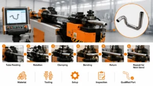
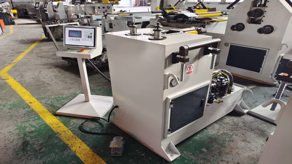
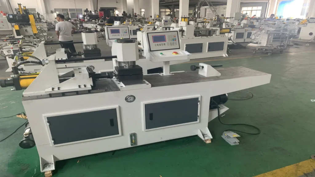
ZR’s DW38CNC-3A-1S documentation lists servo-controlled feeding, tube rotation, and bending, plus springback compensation settings and slow-bend and slow-mandrel-withdrawal functions. Those features provide control options; they do not constitute proof that a particular defect will disappear.
Review the ZR CNC pipe bending machine range with your component requirements. Confirm model-specific functions and validate the proposed setup through an agreed trial. A larger capacity rating alone does not establish a better result.
What to Send ZR for a Bending Review
Provide enough information to connect the visible problem with the component and process:
- Drawing or model, revision, and critical acceptance requirements.
- Material grade and condition, outside diameter, and wall thickness.
- Centerline bend radius, angles, straight lengths, and bend orientation.
- Overall and close-up photographs showing the affected location.
- Current machine and tooling configuration.
- Adjustments already attempted, measured results, batch size, and output requirements.
ZR can review drawings and discuss process steps, tooling design, setup, and training requirements. Agree the scope before committing to equipment or tooling.
For ordered equipment, ZR’s stated arrangement is testing after the deposit and before shipment, followed by acceptance, balance payment, and dispatch. Confirm trial criteria, commercial terms, on-site training, travel costs, and support arrangements.
Tube Bending Defects: Frequently Asked Questions
Is springback itself a tube bending defect?
Springback is elastic recovery after unloading. The resulting angle or geometry becomes a quality problem when it falls outside the applicable requirements. Measure the released part and establish compensation through validated trials rather than treating all recovery as a defect.
Does every tube bend need a mandrel and wiper die?
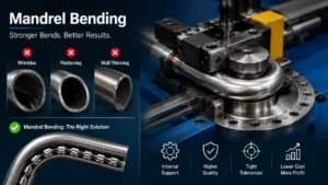
No. The requirement depends on the tube, bend geometry, process, and acceptance criteria. A mandrel provides internal support; a wiper addresses specific wrinkling conditions near the bend tangent. Confirm the tooling arrangement for your component rather than adding both by default.
Can increasing pressure make a bending defect worse?
Yes. Raising pressure-die force can increase drag, while excessive clamping force can mark the gripping area. Identify the setting involved and follow the approved setup procedure. Do not treat increased pressure as a general remedy for tube bending defects.
Why do tube bending defects appear after a material batch or tooling change?
A change may affect dimensions, material behavior, tool fit, or setup. Compare the previous and current conditions using records and measurements. The timing helps direct the investigation but does not prove that the changed item is the only cause.
How can I tell whether a defect was present before bending?
Inspect and document representative incoming stock, then compare it with formed samples. Track sample identity and the affected location. If your available inspection cannot establish whether a suspected flaw was already present, involve the material supplier and qualified inspection personnel.
Can a CNC tube bender prevent all tube bending defects?
No. CNC control can repeat programmed movements, but acceptable parts also depend on material, tooling, setup, and inspection. Verify the complete process with representative stock and agreed acceptance criteria. Programming capability alone is not a guarantee of defect-free production.
Send your drawing, defect photographs, and measurements to ZR’s contact team to discuss the checks, tooling, and machine configuration relevant to your tube bending defects.