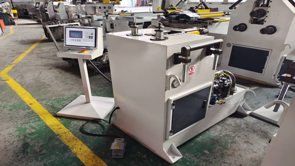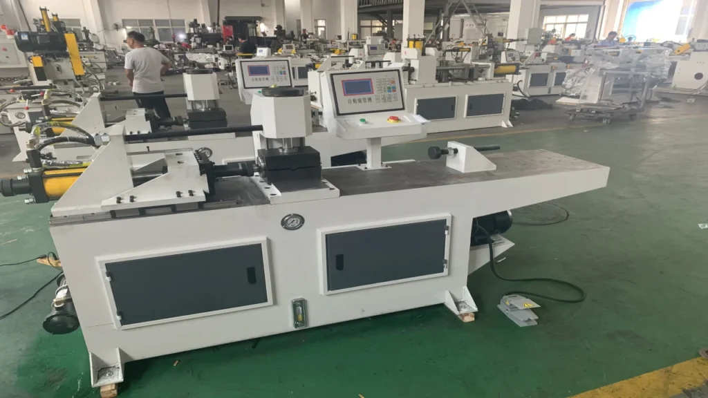
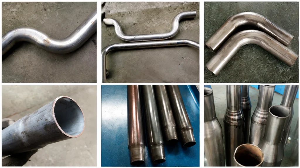
Tube fabrication turns straight tube, cut blanks, or coiled tubing into finished parts and assemblies. A production route may include cutting, bending, rolling, end forming, notching, joining, and inspection. The required steps depend on the finished-part drawing.
For an equipment buyer, the drawing identifies the material, geometry, end features, tolerances, and mating parts. Engineers use it to set the process sequence, tooling, and inspection points before comparing machine configurations.
What Is Tube Fabrication?
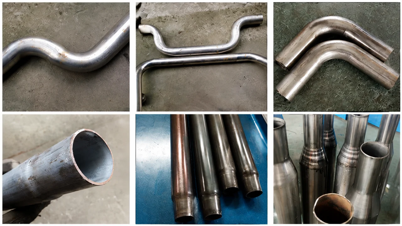
Tube fabrication covers the operations that change purchased tubing into a usable component. A route may include cutting, bending, notching, joining, and inspection. The required operations change with the part.
Tube Fabrication vs. Tube Manufacturing
Tube manufacturing produces the tube itself. Welded-tube mills form and join strip, while seamless production can pierce, extrude, roll, or draw a billet.
Tube fabrication starts with tube stock that already has a defined cross-section and wall thickness. The fabricator changes its length, path, ends, or assembly features. Keeping this boundary clear prevents an equipment team from comparing a tube mill with a tube bender or end-forming machine.
Tube Fabrication vs. Tube Forming
Tube forming changes geometry through bending, rolling, expanding, reducing, flaring, or swaging. Fabrication also covers material removal, joining, finishing, and inspection.
Tube Fabrication vs. Pipe Fabrication
Manufacturers tend to specify tube by outside diameter and wall thickness. Pipe specifications often focus on nominal size, schedule, pressure service, and connections. Pipe fabrication commonly includes cutting, beveling, fit-up, welding, and spool preparation. Industry usage overlaps, so buyers should describe the part and application.
Start with the Finished-Part Drawing
A machine catalog cannot show whether a model can produce your part. The drawing contains the information needed to plan the work.
Check the Material and Tube Dimensions
Record the material grade, outside diameter, wall thickness, profile, and surface requirement. State whether the raw tube has a weld seam and whether its orientation affects the part.
Two tubes with the same outside diameter can require different tooling because wall thickness, hardness, weld condition, and finish affect clamping and forming.
Identify the Finished Geometry
Mark each feature that changes the straight tube:
- Finished or blank length
- Bend radii, angles, and planes
- Straight distances between bends
- Expanded, reduced, flared, or closed ends
- Chamfers, holes, slots, and saddle notches
- Joining surfaces and mating components
Short straight sections can restrict clamping. Formed or notched ends can interfere with later tooling, so their position affects the sequence and fixtures.
Define Critical Dimensions and Datums
Separate functional dimensions from reference dimensions. A frame bracket may need tight control of bend angle and end position to fit its welding fixture.
The drawing should identify the datum scheme and tolerance for each critical feature. The supplier can then plan the first-piece inspection around the same references. A general machine-accuracy statement cannot replace a part-specific inspection plan.
| Drawing feature | Likely process | Equipment direction |
|---|---|---|
| Fixed blank length | Cutting | Tube cutting machine |
| Controlled small-radius bend | Rotary draw bending | NC or CNC tube bender |
| Large continuous curve | Roll bending | Tube rolling machine |
| Expanded, reduced, or flared end | End forming | Tube end-forming machine |
| Angled end preparation | Chamfering | Pipe chamfering machine |
| Saddle-shaped joint end | Arc notching | Tube notching machine |
| Multi-part structure | Joining or welding | Downstream assembly equipment |
The table provides a starting point. The drawing, material, and production target determine the final method.
Main Tube Fabrication Processes
Tube Cutting
Cutting establishes the blank length and often creates the first production datum. The process must also control squareness, burrs, end deformation, and surface damage. A poor cut can affect bend location, end forming, welding gaps, and operator safety.
Projects may use sawing, shearing, laser cutting, abrasive cutting, or a chipless method. Material, profile, tolerance, cut quality, and output determine the choice.
ZR offers several pipe cutting machine configurations for different tube and production requirements. Buyers should submit the material and cut specification instead of selecting a saw by maximum diameter alone.
Tube Bending
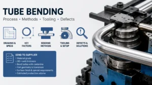
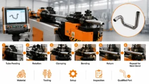
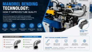
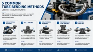
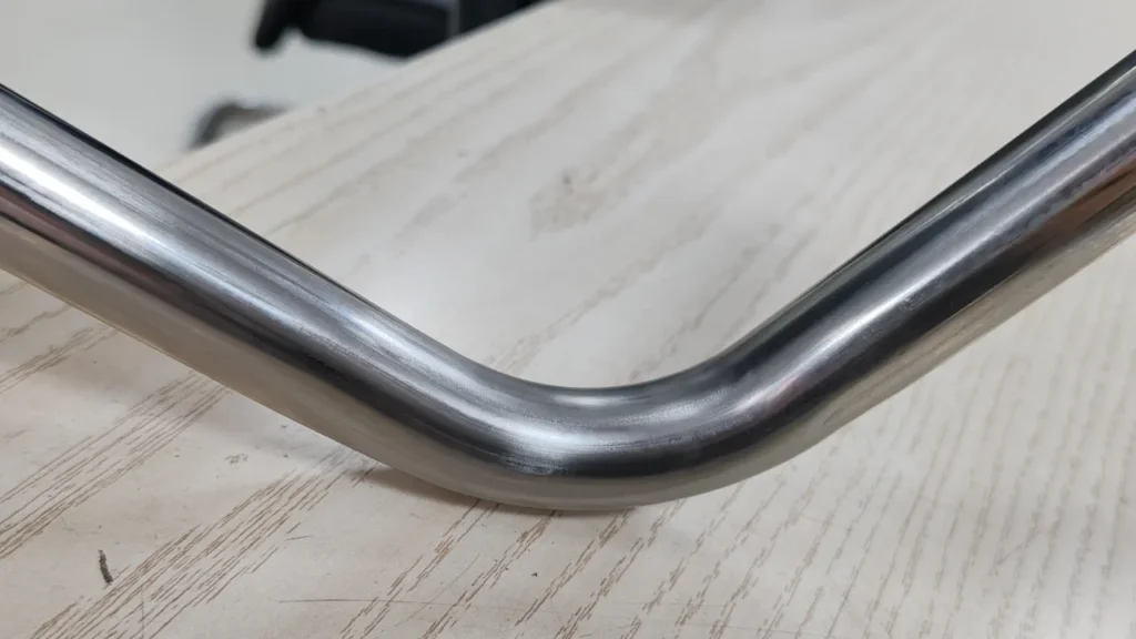
Tube bending forms one or more angles while controlling the tube cross-section. Rotary draw bending uses a matched tool set to pull the tube around a bend die. Compression bending presses the tube around a form. Roll bending produces large radii and continuous curves.
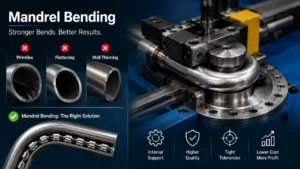
Outside diameter, wall thickness, centerline radius, material, and allowed deformation determine the tooling. Tight radii and thin walls may require a mandrel or wiper die.
Parker’s tube-bending guidance links mandrel selection to wall thickness and bend radius. Its chart uses the outside-diameter-to-wall-thickness and centerline-radius-to-outside-diameter ratios. A production-material sample provides stronger evidence for the final setup.
Buyers can compare CNC pipe bending machines with NC pipe bending machines after defining the part, loading method, output, and inspection requirements.
Tube Rolling
Roll bending forms broad curves, arcs, and rings by passing the tube through rolls. The drawing should state the radius, chord, arc length, profile orientation, and permitted distortion. ZR’s tube rolling machine range covers this fabrication stage.
Tube End Forming
End forming changes the open end so it can connect, seal, locate, or fit another component. Common forms include expansion, reduction, flaring, beading, tapering, and closing.
The engineer needs a detailed end-profile drawing. Forming length, transitions, local radii, material, and mating dimensions affect die design and the number of stages.
The tube end-forming machine range provides a starting point for equipment review. ZR must confirm the machine and tooling against the finished-end geometry.
Chamfering, Deburring, and Arc Notching
Chamfering cuts an angled end surface, deburring removes sharp material, and arc notching creates a saddle profile for a mating tube. A notch specification needs the mating diameter, joint angle, direction, and position. ZR lists pipe chamfering machines for separate end-preparation work.
Welding, Joining, and Assembly
Some routes continue into welding, brazing, or assembly. Cut quality changes the joint gap, bend accuracy changes fixture fit, and notch position changes where tubes meet. ZR supplies tube-processing machinery rather than a fabrication job-shop service, so each proposal should state the operations covered.
Finishing and Inspection
Cleaning, coating, marking, or packaging may follow forming. Inspection should start with incoming material and continue through cut length, first-piece bends, and end-profile checks.
How to Determine the Correct Process Sequence
The process planner should review how each operation changes the part and its available locating surfaces.
Begin with the Raw-Material Form
Coil-fed tubing can support several connected operations. Long straight stock may suit an automatic loader and saw, while pre-cut blanks support flexible batches. Material form affects handling, cut strategy, automation, and available gripping positions.
Protect Clamping Surfaces and Datums
Each machine needs enough straight tube to clamp and locate the workpiece. A bend placed too close to an end can block a later fixture. An end form can remove the cylindrical surface needed for bending. A notch made before bending can rotate away from the required assembly position if the operator uses the wrong reference.
Process planners should mark the datum used at each station and confirm that the previous operation preserves it.
Check the Effect on the Next Operation
Cut length influences bend position. Bending establishes the final orientation of the ends. Notching prepares those ends for a mating tube. Welding can add distortion that the final fixture must control.
A useful route gives each station a stable input and a measurable output. The team should revise the sequence when one operation damages a finished feature or removes a locating surface.
Use a Part-Specific Sequence
Some parts need end forming before bending or final cutting after forming. Engineers should choose the sequence from the drawing, tooling access, tolerance chain, and assembly.
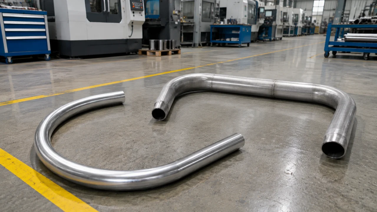
Example: Planning an E-Bike Frame Support Bracket
ZR reviewed a representative support bracket for an electric-bike frame. This engineering example shows how a finished drawing can guide process and equipment decisions. The target output remains a planning requirement rather than a published mass-production result.
Read the Part Requirements
The part uses Q235 round tube with a 25 mm outside diameter and 2 mm wall. The approximate cutting length is 370 mm. The finished geometry has two 40-degree bends with a 60 mm centerline radius. The specified bend-angle tolerance is plus or minus 0.1 degree.
Both ends need saddle-shaped notches that fit 35 mm mating tubes. The production target is 800 accepted parts during an eight-hour shift.
Map the Features to Operations
| Part requirement | Required operation |
|---|---|
| Approximate 370 mm blank | Tube cutting |
| Two R60, 40-degree bends | Tube bending |
| Ends fitting 35 mm mating tubes | Double-end arc notching |
| Bend-angle tolerance of ±0.1° | First-piece and batch angle inspection |
| 800 accepted parts per shift | Cycle-time and line-balance review |
ZR recommends cutting the blank, forming both bends, and then notching both ends. Bending first establishes the final end orientation. The notching station can then locate the formed part and align each saddle with the intended mating tube.
This sequence belongs to this bracket. A different part may need another order because its clamping surfaces, end features, or assembly datums differ.
Select the Equipment
The route requires a tube cutting machine, an NC or CNC tube bender, and a CH60NC arc-notching machine. The 25 mm outside diameter alone cannot determine the final cutting or bending model. ZR also needs the loading plan, cycle requirement, material sample, inspection method, and allowed section deformation.
ZR proposed a CH60NC with application-specific tooling for the notches that fit the 35 mm mating tubes. The final machine and tool design still require confirmation against the complete joint geometry and notch orientation.
Review the Mandrel Requirement
This part has a wall thickness equal to 8 percent of its outside diameter. Its outside-diameter-to-wall-thickness ratio is 12.5, and its centerline-radius-to-outside-diameter ratio is 2.4.
Those ratios support an initial tooling review but do not settle the decision. ZR can test a mandrel and non-mandrel setup with representative Q235 tube. The approved method should meet the agreed limits for angle, ovality, wrinkles, surface condition, and cycle time.
Calculate the Required Production Pace
An eight-hour shift contains 28,800 seconds. Dividing that time by 800 accepted parts gives an average takt of 36 seconds per finished part.
The 36-second figure describes the complete workflow output. It does not prove that one machine has a 36-second cycle. The production plan must include loading, cutting, bending, notching, transfer, inspection, planned stops, and rejected parts. A bottleneck at one station may require process improvement or parallel capacity.
Set the Quality Checkpoints
The inspection plan should check the incoming tube specification and surface before cutting. After cutting, the operator should verify blank length, end condition, and the datum used for bending.
The first bent part needs checks for both R60 bends, both 40-degree angles, the ±0.1° angle tolerance, central geometry, section deformation, and surface marks. After notching, the inspector should verify the saddle profile, orientation, and fit against the 35 mm mating tube. A final fixture can confirm the dimensions that control frame assembly.
ZR and the buyer should agree on the measuring method, inspection datums, sampling frequency, and acceptance record before the equipment test.
Choose the Equipment Configuration
Factories can arrange tube fabrication equipment as standalone machines, a coordinated cell, or an integrated line. Product mix and verified cycle data should guide the choice.
Standalone Machines
Separate machines support varied parts and changing routes. They reduce integration work but add handling and work-in-process inventory.
Coordinated Production Cell
A production cell arranges separate machines around a stable part family. Fixtures and transfer methods protect orientation and reduce movement.
Integrated Automated Line
An automated line connects feeding, processing, transfer, and unloading. It suits stable products, material, and cycle requirements. Teams should validate each operation before integration because automation cannot correct material or setup variation.
| Decision factor | Standalone machines | Coordinated cell | Automated line |
|---|---|---|---|
| Product variety | High | Medium | Low to medium |
| Output pattern | Variable | Stable | Stable and repeatable |
| Manual handling | High | Medium | Low |
| Changeover flexibility | High | Medium | Depends on line design |
| Integration effort | Low | Medium | High |
| Main evaluation | Process flexibility | Line balance | Verified cycle and investment case |
Place Quality Checks Throughout the Process
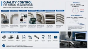
Incoming inspection should confirm material identity, OD, wall thickness, straightness, and surface. In-process checks should follow the features created at each station. First-piece approval should record the drawing revision, material, tooling, setup, datums, and accepted values. The buyer and supplier should set batch-inspection frequency from process risk and customer requirements.
Information an Equipment Supplier Needs
Prepare the following information before requesting a machine recommendation:
- Finished-part drawing or 3D model
- Material and grade
- Outside diameter and wall thickness
- Tube profile and weld-seam information
- Bend radii, angles, and planes
- Straight lengths and end features
- Critical dimensions, datums, and tolerances
- Surface requirements
- Hourly or daily output and number of shifts
- Product mix and changeover frequency
- Current production method
- Required loading and automation level
- Representative sample material
ZR’s design and engineering team can use these inputs to review the process and tooling scope. The company’s sample service can support part testing under the commercial terms agreed for the project.
Planning a tube fabrication process? Send the finished-part drawing, tube specification, tolerances, and output target for an equipment review.
Frequently Asked Questions About Tube Fabrication
What is included in tube fabrication?
Tube fabrication can include cutting, bending, rolling, end forming, chamfering, notching, joining, finishing, and inspection. A finished-part drawing determines which operations the part needs. A factory should avoid adding equipment or process stages that do not create a required feature or support production control.
What is the difference between tube fabrication and tube manufacturing?
Tube manufacturing produces tubing from strip, plate, billet, or another raw form. Tube fabrication starts with manufactured tube stock and turns it into a component or assembly. Common fabrication operations include cutting, bending, end forming, notching, and joining.
Should you cut a tube before or after bending?
Many routes cut a blank before bending, but the best sequence depends on raw-material form, feeding method, bend position, clamping length, tolerance, and equipment. Coil-fed systems may cut during a connected process. Some parts need final trimming after bending to control end position.
Does tube bending require a mandrel?
Mandrel need depends on the tube outside diameter, wall thickness, centerline radius, material, and permitted deformation. Thin walls and tight radii tend to need more internal support. A trial with production material can confirm whether the part meets its ovality, wrinkle, and surface requirements.
What equipment is used for tube fabrication?
Common equipment includes tube saws, CNC or NC benders, roll benders, end formers, chamfering machines, notching machines, punching systems, and inspection fixtures. Automated projects may also use loaders, feeders, robots, and transfer systems.
How do you choose between standalone machines and an automated line?
Compare product variety, output stability, changeover frequency, labor, transfer time, and verified machine cycles. Standalone machines favor flexibility. An automated line favors stable, repeatable production with enough volume to support the integration work.
What information should a tube drawing include?
The drawing should define the material, tube dimensions, bend radii and angles, straight sections, end features, datums, critical tolerances, surface requirements, and mating parts. The equipment supplier also needs the output target and sample material to plan tooling and validation.
Plan the Process Before Selecting the Machine
Start the equipment review with the finished-part drawing and production target. Define the operations, sequence, tooling, inspection points, and material flow. The resulting process plan gives you a sound basis for comparing machine configurations.
Send ZR your drawing, tube specification, critical tolerances, and required output for an equipment and process review. The team can then discuss the machine scope, tooling, sample test, installation, and training terms for your project.
References
- Parker Hannifin, Hydraulic Tube Bender: Thin Wall Tube Bending with Mandrel Equipment
- Parker Hannifin, Principles of Tube Line Fabrication
- Zhuoran Machinery, company-provided e-bike frame support bracket drawing and process notes, supplied August 24, 2026