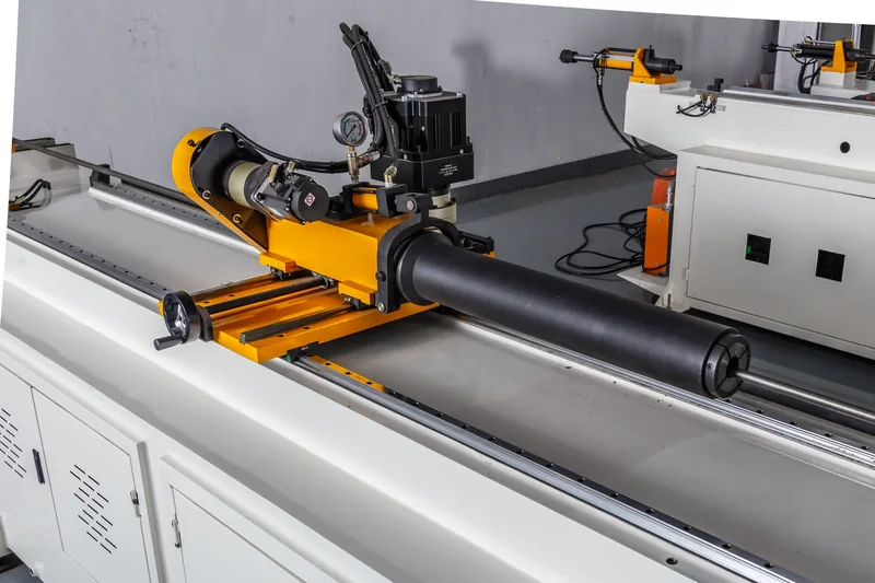
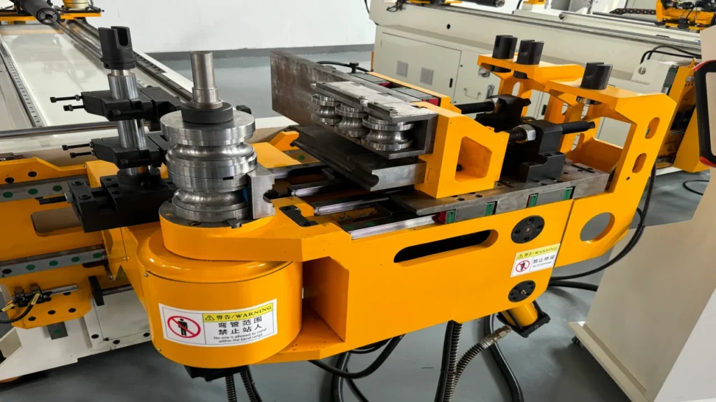
3D tube bending forms a tube through several planes and directions, rather than producing bends on one flat plane only. The result may look simple on a drawing, but the production data must control feeding, tube rotation, bend angle, bend radius, tool movement and inspection together.
For that reason, successful 3D tube bending is not only a machine-selection decision. It is a data and process decision. You need a complete tube definition, a suitable tooling package, a repeatable CNC program and an inspection method that matches the drawing.
This guide explains how to move from a 3D drawing to a production-ready bending process. It also shows what you should confirm before requesting a quotation from Zhuoran.
What Is 3D Tube Bending?
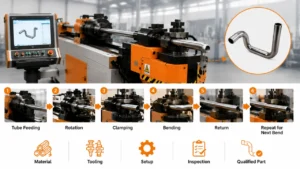
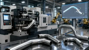
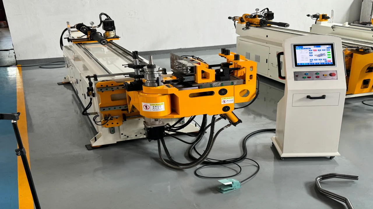
3D tube bending is the controlled forming of a tube along multiple spatial directions. The machine normally coordinates tube feeding, rotation and bending so that each bend is created at the required position and orientation.
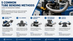
The term does not automatically describe one machine structure or one tooling method. A 3D part may be produced on a CNC rotary-draw bender, a multi-stack machine, a machine with mandrel tooling, or a project-specific automated cell. The correct configuration depends on the tube, geometry, material, tolerances and production volume.
In practical production, a 3D tube bending process usually includes:
- a 2D drawing, 3D model or tube centerline definition;
- material grade and material condition;
- outside diameter and wall thickness;
- centerline radius, bend angles and bend sequence;
- straight lengths and tube-end orientation;
- feed and rotation data;
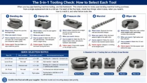
- bending, clamping, pressure and support tooling;
- first-part inspection and program correction.
If any of these inputs is missing, the supplier may be unable to judge feasibility or quote the correct tooling.
2D vs 3D Tube Bending: The Difference Is More Than the Number of Bends
2D bending normally keeps the bend centerlines in one plane. 3D tube bending adds spatial rotation, so consecutive bends can face different directions. A part can therefore require both a bend angle and a rotation angle for each step.
For example, a tube may contain a 90-degree bend followed by a 45-degree bend rotated 90 degrees from the first bend plane. The machine must position the tube correctly before the second bend. A small rotation error can move the final tube end even when the bend angle itself is correct.
This is why 3D bending programs should define a datum, coordinate direction, bend sequence, rotation direction and inspection reference. The drawing should not rely only on a picture of the finished part.
For background on machine motion and control, see How Does a CNC Tube Bender Work?.
What Should a 3D Tube Drawing Include?
Before you ask for a quotation, provide enough information for the supplier to reconstruct the part. A useful drawing package should include the following:
| Input | What to provide | Why it matters |
|---|---|---|
| Material | Grade, temper, heat treatment and surface condition | Material strength and ductility affect springback, thinning and cracking |
| Tube size | Outside diameter and wall thickness | Determines machine capacity, tooling size and support method |
| Bend geometry | Bend angle, centerline radius and bend direction | Defines the forming load and tooling geometry |
| Spatial position | Rotation angle, coordinate system and tube-end orientation | Controls the 3D relationship between bends |
| Straight lengths | Tube end to tangent point and distance between bends | Controls feed length and interference risk |
| Tolerances | Length, angle, position, profile and surface requirements | Defines inspection and acceptance criteria |
| Production | Annual demand, batch size and target cycle time | Helps select manual, NC, CNC or automated equipment |
Send the 3D model together with a dimensioned drawing whenever possible. The model helps describe spatial geometry, while the drawing defines the dimensions and tolerances that must be accepted.
From CAD Model to CNC Bend Program
The normal workflow is drawing review, geometry extraction, bend-sequence planning, machine and tooling evaluation, first-part production, measurement and correction. A 3D model alone does not remove the need for process engineering.
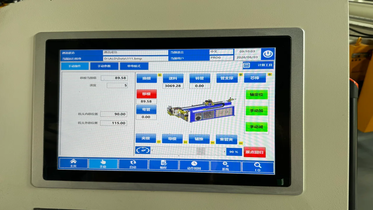
For Zhuoran’s current workflow, STEP file import and collision simulation are handled through the industrial computer system. The CAD system itself does not provide STEP import or collision simulation in this workflow. Therefore, if your project requires these functions, ask the supplier to list the applicable industrial computer system and software configuration in the quotation and technical agreement.
- Confirm the datum, tube axis and coordinate directions.
- Extract bend points, straight lengths, radii, angles and rotations.
- Select a bend sequence that avoids tool, machine and part interference.
- Check the tube against the available bend die, clamp die, pressure die and support tooling.
- Generate or enter the CNC data.
- Run collision simulation through the applicable industrial computer system when included in the configuration.
- Produce a first sample and measure the critical dimensions.
- Compensate for springback and process variation.
- Lock the approved program and inspection method before volume production.
The exact software workflow depends on the machine model and quoted configuration. Do not assume that a CAD file can be imported directly into every control system.
How Are XYZ, LRA and YBC Data Used?
XYZ, LRA and YBC are different ways to describe the same basic tube-bending geometry. The selected format must match the machine control system and the supplier’s programming workflow.
| Data format | Typical meaning | Use in production |
|---|---|---|
| XYZ | Coordinate points in space | Describes centerline points and spatial position |
| LRA | Length, rotation and angle | Defines feed length, tube rotation and bend angle |
| YBC | Feed, bend angle and rotation | Common machine-oriented representation for bend sequences |
Do not convert between formats without checking the datum and direction conventions. A sign change, reversed rotation direction or different tangent-point definition can create a large position error at the end of a multi-bend tube.
The supplier should confirm which data format the selected control system accepts, who converts the file, and how the approved program is stored and revised.
Machine and Tooling Configuration for 3D Tube Bending
The machine must be evaluated as a complete forming system. A large nominal machine size does not automatically mean that it can produce your part accurately.
| Component or function | Purpose | Configuration question |
|---|---|---|
| CNC control | Stores and coordinates the bending sequence | Which axes and functions are included? |
| Feed axis | Moves the tube to each bend position | What feed length and repeatability are required? |
| Rotation axis | Sets the spatial orientation of the tube | Is three-dimensional rotation available for the part? |
| Bend die | Forms the tube around the required radius | Does the die match the OD, CLR and material? |
| Clamp die | Holds the tube during bending | Is the grip length adequate without damaging the surface? |
| Pressure die | Supports the tube and controls material flow | Is pressure-die assistance required for the geometry? |
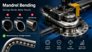
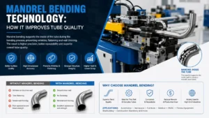
| Mandrel | Supports the tube inside the bend | Is it required for the wall thickness, CLR and ovality limit? |
| Wiper die | Supports the inside of a tight bend near the tangent | Is wrinkle control required? |
| Multi-stack tooling | Allows different radii or tools on one setup | Does the part require multiple CLR values? |
| Loading and unloading | Reduces handling time | Is automatic loading or unloading required? |
| Inspection | Confirms critical dimensions and defects | Which gauges, CMM or profile checks are needed? |
For a general overview of bending methods, see Tube Bending Process and Tube Bending Technology.
When Do You Need CNC, Mandrel, Wiper Die or Multi-Stack Tooling?
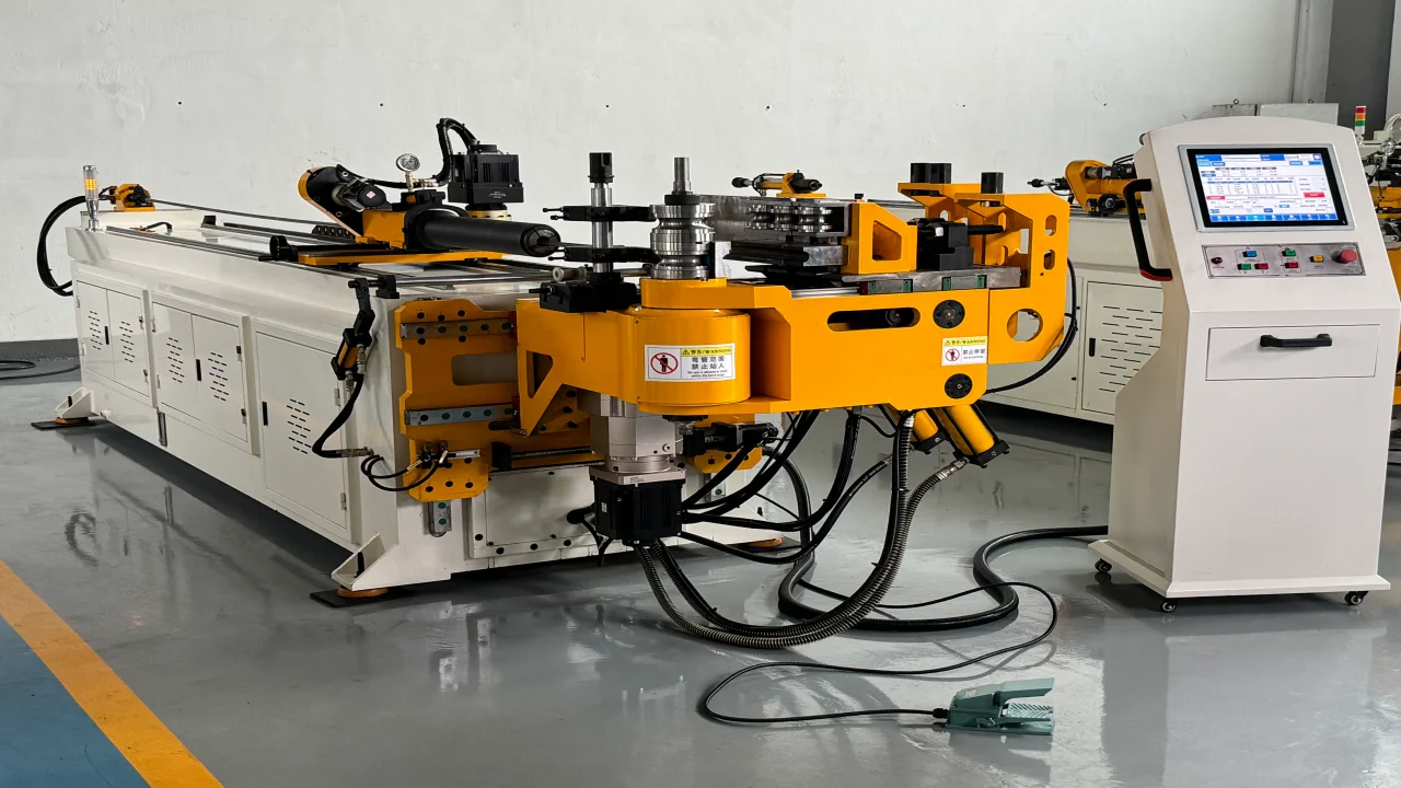
You need CNC control when the part requires repeatable feed, rotation and bend positioning across several spatial bends, especially when production involves multiple part numbers or frequent program changes.
You may need mandrel tooling when the tube is relatively thin-walled, the bend radius is tight, or the finished part has strict ovality and cross-section requirements. A mandrel does not solve every forming problem; its design and position must match the tube and process.
You may need a wiper die when material tends to wrinkle at the inside of a tight bend. The need depends on the material, wall thickness, radius, lubrication and tooling setup.
You may need multi-stack tooling when one part family uses more than one bend radius or when several tools must remain available during production. The machine must be structurally designed to support the required stack.
These decisions should be made from the actual tube drawing and sample trial, not from the keyword “3D” alone.
How Do Material, OD, Wall Thickness and CLR Affect Feasibility?
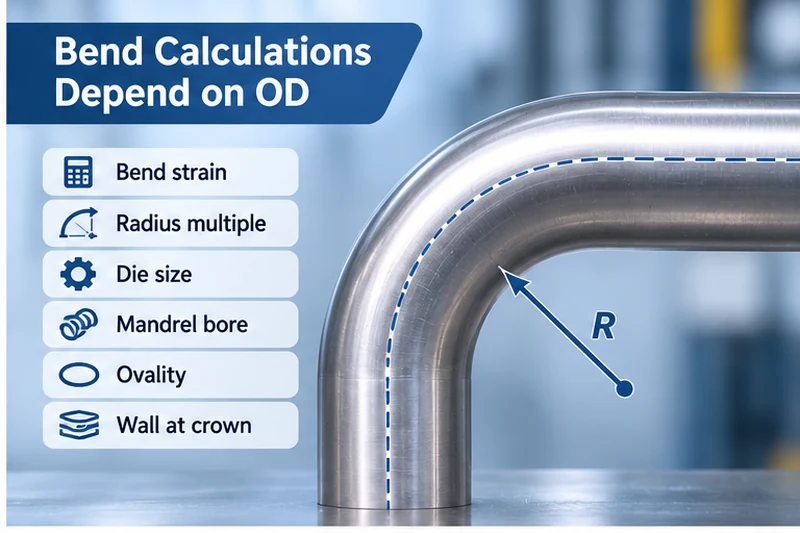
Material and geometry determine how much the tube can deform before ovality, thinning, wrinkles or cracks become unacceptable. The same machine can produce different results on two materials with the same outside diameter because yield strength, work hardening, elongation and temper are different.
The main inputs are:
- outside diameter and wall thickness;
- diameter-to-wall-thickness ratio;
- material grade and heat-treatment condition;
- centerline radius and CLR-to-OD ratio;
- bend angle and number of bends;
- distance between adjacent bends;
- surface and appearance requirements;
- allowable ovality, thinning and dimensional deviation.
Zhuoran’s current engineering reference for the minimum bend radius is 1.5D, where D is the tube outside diameter. For example, a 38 mm tube would have a reference CLR of 57 mm at 1.5D.
This is a reference for feasibility discussion, not a universal guarantee. The actual minimum radius must be confirmed using the material, wall thickness, bend sequence, tooling, surface requirement and sample result.
Zhuoran Engineering Reference Values
The following values were provided as current engineering reference data for this article:
| Item | Reference value | Important limitation |
|---|---|---|
| General accuracy reference | 0.1 mm | Confirm whether the project requires machine accuracy, feed accuracy, position accuracy or finished-part accuracy |
| Minimum reference bend radius | 1.5D | Actual result depends on tube size, material, wall thickness, tooling and bend geometry |
| General qualified-rate reference | 98% | Confirm the sample size, inspection standard and production conditions |
These values should be included in a quotation or technical agreement only after they are matched to the selected model and the customer’s part. They should not be treated as automatic guarantees for every 3D tube bending project.
Common Quality Risks in 3D Tube Bending
Springback
The tube may open or rotate slightly after the bending load is released. Springback is affected by material strength, wall thickness, radius and bend angle. The correction should be based on measured samples rather than a generic compensation value.
Ovality and local collapse
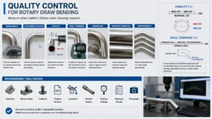
The cross-section can become oval or locally collapse when the radius is tight, the wall is thin or the support is insufficient. Measure the maximum and minimum outside diameter at the critical section when ovality matters.
Wall thinning and cracking
The outside of a bend is placed in tension and may become thinner. Excessive thinning can reduce structural performance and may lead to cracks, especially with high-strength or work-hardening materials.
Wrinkles and surface damage
Wrinkles may appear on the inside of the bend when material flow is not controlled. Scratches and clamp marks can also cause rejection when the tube is visible or requires a coating finish.
Spatial and accumulated position error
Small errors in feed, rotation or angle can accumulate across several bends. For this reason, the inspection plan should check the final tube profile and tube-end positions, not only individual bend angles.
For related defect terminology, see Tube Bending Defects.
How Should 3D Tube Bending Be Validated Before Production?
Validate the actual part with the actual material and tooling. A machine brochure or an isolated bend sample cannot prove that the complete 3D tube will meet your drawing.
- Confirm the material certificate, OD, wall thickness and tube condition.
- Confirm the drawing datum, bend sequence, rotations and critical tolerances.
- Confirm the machine model, control system, tooling and industrial computer functions.
- Produce a first sample using the proposed process.
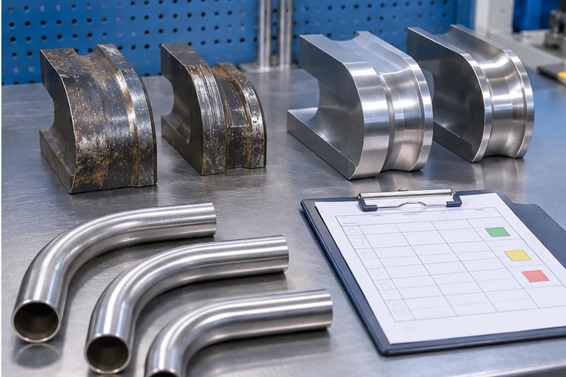
- Measure cut length, bend angles, bend positions, tube-end positions and profile.
- Check ovality, wall thinning, wrinkles, cracks, burrs and surface damage where applicable.
- Adjust the program or tooling based on measured results.
- Run a repeatability or continuous-production trial.
- Approve the final program, inspection standard and acceptance record.
For production evaluation, use the following formula:
Qualified rate = Good pieces ÷ Total tested pieces × 100%
The 98% qualified-rate figure supplied for this article is a general engineering reference. It should be confirmed against the customer’s actual sample size, part geometry, quality limits and operating conditions.
Automotive is where 3D geometry pays off most: exhaust, chassis and bracket parts rarely sit in a single plane, and it is the multi-plane requirement — not the bend count — that forces a four- or five-axis machine. The application side is covered in multi-plane automotive parts.
3D Tube Bending RFQ Checklist
Send the following information when requesting a machine recommendation or quotation:
| RFQ item | Information to include |
|---|---|
| Part files | Dimensioned 2D drawing and 3D model, if available |
| Material | Grade, temper, heat treatment and surface condition |
| Tube size | OD, wall thickness and raw-tube length |
| Bend data | Bend sequence, angle, CLR, rotation and straight lengths |
| Tolerances | Length, angle, position, profile and surface requirements |
| Quality | Ovality, thinning, wrinkle, crack and appearance limits |
| Production | Batch size, annual demand and target output |
| Automation | Loading, feeding, rotation, unloading, inspection and sorting needs |
| Software | STEP import, collision simulation, data format and program transfer requirements |
| Acceptance | Sample quantity, inspection tools, FAT/SAT and approval documents |
Ask the supplier to separate standard configuration, optional functions, tooling, automation, installation, training, sample trials, transport and excluded items in the quotation.
What Should You Send to Zhuoran for a 3D Tube Bending Recommendation?
Send the 2D drawing and 3D model first. Then add the material grade and condition, tube OD, wall thickness, centerline radius, bend sequence, rotation angles, tube-end orientation, tolerances, surface requirements and expected production quantity.
Also state whether your project requires:
- STEP import through the industrial computer system;
- collision simulation through the industrial computer system;
- mandrel or wiper-die support;
- multi-stack tooling;
- automatic loading, unloading or inspection;
- a specific qualified-rate target;
- a sample trial and formal acceptance report.
The more complete the data package, the easier it is to recommend a suitable machine and avoid an incomplete quotation. The final model, tooling package, accuracy target, minimum radius and production result should be confirmed by an engineering review and technical agreement.
Practical FAQs About 3D Tube Bending
Can Zhuoran’s system import STEP files?
STEP import is available through the industrial computer system in Zhuoran’s current workflow. The CAD system itself does not support STEP import in this workflow. Confirm the industrial computer configuration, software scope and supported file versions before ordering.
Does Zhuoran’s system support collision simulation?
Collision simulation is supported through the industrial computer system. It is not a standard CAD-system function in the described workflow. The quotation should identify whether this function is included for the selected machine and software configuration.
What is the minimum bend radius?
Zhuoran’s current engineering reference is 1.5D. The actual minimum radius depends on tube OD, wall thickness, material, bend angle, tooling, surface requirements and sample validation.
What accuracy can I expect?
The general engineering reference supplied for this article is 0.1 mm. Before treating it as an acceptance value, confirm what type of accuracy it describes and validate the finished part using the agreed inspection method.
Is 3D tube bending the same as 3D printing?
No. 3D tube bending is a forming process that reshapes a metal tube through controlled feed, rotation and bending. It is not additive manufacturing or tube 3D printing.
Do I always need a mandrel?
No. Mandrel support depends on the material, wall thickness, bend radius, ovality limit and surface requirements. The tooling should be selected from the actual part and sample result.
How should I compare a tube bending machine quotation?
Compare the complete scope: machine, control system, industrial computer functions, tooling, automation, inspection, sample trial, installation, training, warranty, delivery and excluded items. Comparing only the machine price can hide missing tooling or automation costs.
References and Technical Resources
- Tidyco: Tube Bending
- Sharpe Products: Dimensional Inspection of Tube Bending
- Hexagon: BendingStudio
- HTP: Tube Bending Technology
- Vogel: 3D Tube Bending Service
- Numalliance: 3D Tube Bending Machine
These external resources are provided for technical context. Zhuoran’s final machine configuration and performance should be confirmed through the part drawing, sample trial, inspection report and technical agreement.