Exhaust system manufacturing combines tube preparation, forming, joining, inspection, and assembly. In many programs, the tube-processing stage determines whether the final exhaust part fits the vehicle package, meets the drawing, and can be produced at the required rate.
This guide focuses on the manufacturing of exhaust tubes and related metal tube components. It explains how exhaust tubes are cut, bent, formed, checked, and prepared for downstream welding and assembly. It does not present Zhuoran as a complete exhaust system, catalytic converter, or emissions-certification supplier.
For automotive applications, see Zhuoran’s automotive tube processing solutions. For a machine recommendation, prepare the material grade, tube OD, wall thickness, bend schedule, end-forming requirements, production target, and inspection requirements before contacting a supplier.
What Does Exhaust System Manufacturing Include?
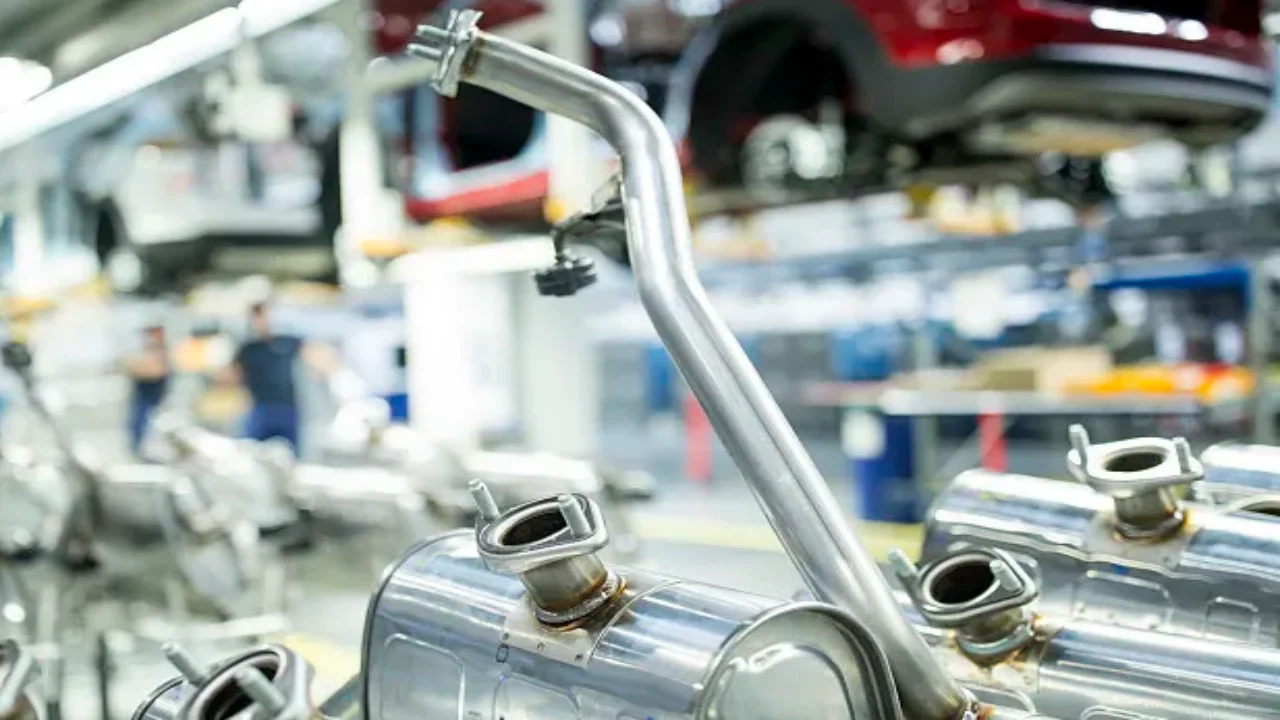
Exhaust system manufacturing includes the production and assembly of components that route exhaust gas, control noise, manage heat, and connect to the vehicle or engine package. Depending on the product, the system may contain bent tubes, expanded or reduced ends, flanges, catalytic converter housings, resonators, mufflers, brackets, shields, and welded subassemblies.
From a tube-processing perspective, the main work is usually divided into the following stages:
- Tube or coil preparation and cutting
- End preparation, such as deburring, chamfering, expanding, reducing, or flaring
- Rotary draw bending or another selected forming process
- Fixture-based fit-up and joining
- Dimensional, visual, and leak-related inspection
- Final assembly, traceability, and packaging
The exact route depends on the part drawing, material, tube geometry, surface requirements, production volume, and downstream welding method. A tube bender is therefore one part of the manufacturing chain, not the entire exhaust system solution.
From Raw Tube to Finished Exhaust Part: The Manufacturing Flow
A typical manufacturing flow starts with material verification and ends with a released part. The sequence can change when a program uses preformed components, hydroformed parts, welded blanks, or special end-forming operations.
- Review the part definition. Confirm the 2D drawing, 3D model, datum, bend sequence, end features, tolerances, and surface requirements.
- Verify the tube input. Check the material grade, OD, wall thickness, incoming tolerance, tube length, and surface condition.
- Cut and prepare the tube. Cut length, burr control, chamfering, and end condition affect later clamping and forming.
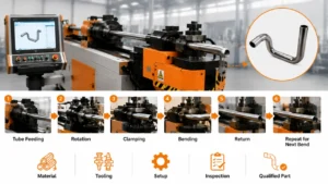
- Bend the tube. The selected tooling and bending method must control springback, flattening, wrinkles, and surface damage.
- Form the tube ends. Expansion, reduction, flaring, beading, or other end features may be produced in a dedicated end-forming operation.
- Fit, weld, and assemble. The formed tube is positioned with fixtures and joined to other components according to the manufacturing process.
- Inspect and release. Check critical dimensions, profile, ovality, wall condition, surface quality, weld-related requirements, and documentation.
This sequence is useful for an RFQ because it separates machine capability from tooling, automation, welding, and inspection responsibilities.
How Exhaust Tubes Are Manufactured
Exhaust tubes are commonly manufactured by combining cutting, tube bending, end forming, joining, and inspection. The correct process is selected from the part geometry and material rather than from the tube diameter alone.
Cutting and tube-end preparation
The tube is cut to a defined length before bending or before a later forming operation. Cutting quality matters because excessive burrs, an incorrect blank length, or a damaged end can affect clamping, end forming, fit-up, and final position.
For production programs, confirm whether cutting is performed by a separate machine or integrated into a line. Zhuoran’s pipe cutting machine range covers cutting equipment, while the exact feed length, saw configuration, automation, and inspection requirements remain project-specific.
Tube bending
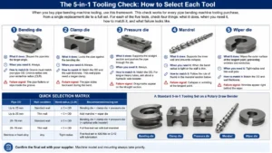
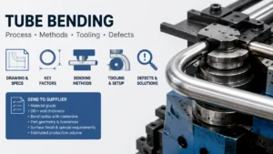
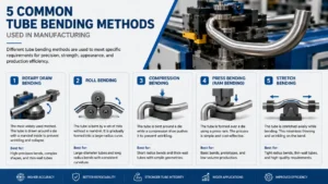
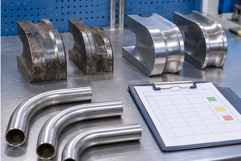
Rotary draw bending is often selected when the exhaust tube requires repeatable centerline geometry, controlled bend locations, and several bends in one part. The process uses a bend die, clamp die, pressure die, and, when required, a mandrel and wiper die.
For a deeper explanation of the process, see the general tube bending process. Those pages should remain focused on bending methods; this article covers bending as one stage within exhaust system manufacturing.
End forming
Exhaust tubes may require an expanded end, reduced end, flare, bead, notch, or another connection feature. End forming is normally selected from the joint design, mating component, sealing method, wall thickness, and required dimensional tolerance.
When end forming is part of the project, review the tube end-forming machine range separately from the bending machine. A bending mandrel is not the same tool as an end-forming punch, internal support, or forming die.
Joining and assembly
After forming, exhaust components may be welded, clamped, bolted, or assembled with other parts. Tube-processing equipment can prepare accurate components, but weld design, fixture design, leak testing, heat treatment, and emissions validation must be specified separately when they are part of the customer program.
Materials and Tube Inputs That Determine the Process
Material grade, wall thickness, OD, incoming tolerance, surface condition, and mechanical properties influence the forming process. Exhaust applications may use stainless steels, aluminized or coated steels, and other grades selected for temperature, corrosion, formability, cost, and service requirements.
Material selection should be confirmed against the customer drawing and application requirements. Technical literature on automotive exhaust materials discusses heat exposure, corrosion, thermal fatigue, and forming requirements; these factors can change the recommended process and tooling.
| Input | Why it matters | What to send the supplier |
|---|---|---|
| Material | Changes forming force, springback, surface behavior, and joining requirements. | Grade, temper or condition, coating, and material standard. |
| Tube OD and wall thickness | Defines the working range and affects flattening and wall reduction. | Nominal size and incoming dimensional tolerances. |
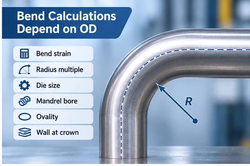
| Centerline radius | Influences the bending difficulty, tooling choice, and need for internal support. | CLR for each bend or the required tangent geometry. |
| Part geometry | Determines feed length, rotation, bend sequence, interference risk, and handling. | 2D drawing, 3D STEP file, datum, bend schedule, and end features. |
| Production requirement | Determines whether manual, NC, CNC, or integrated automation is appropriate. | Annual volume, batch size, shifts, target cycle time, and quality rate. |
Which Equipment and Tooling Are Used for Exhaust Tube Manufacturing?
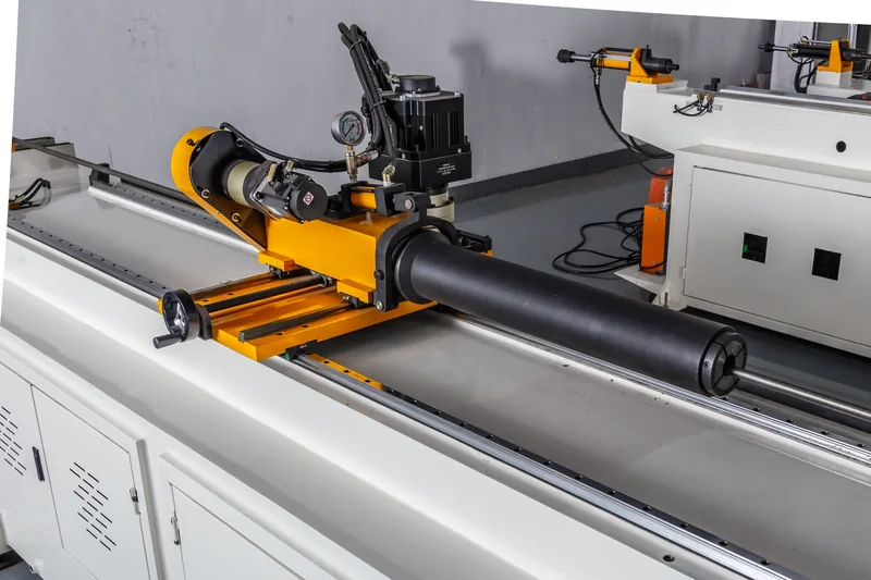
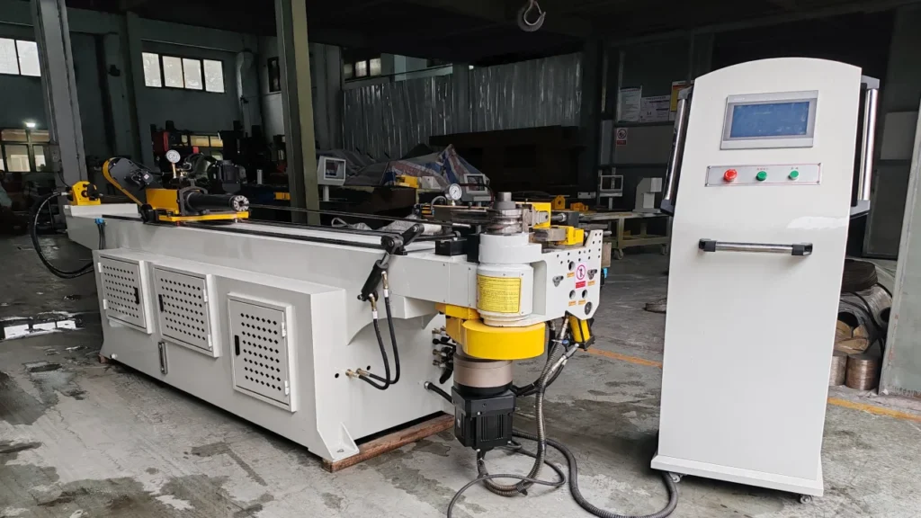
Equipment selection should follow the complete process route. A typical tube-processing cell may include a cutting machine, CNC tube bender, end-forming machine, tooling, loading or unloading equipment, inspection equipment, and a line-level control system.
Bending machine and tooling
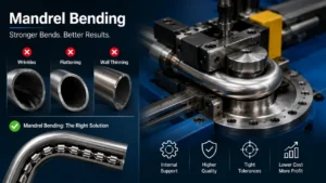
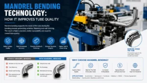
For rotary draw bending, the bend die, clamp die, pressure die, mandrel, and wiper die are selected from the tube size, material, CLR, bend geometry, and surface-quality target. Mandrels and wiper dies are not automatically required for every tube or every bend. Their need should be confirmed by trial bending.
Zhuoran’s pipe bending machine tooling guide can be used together with the customer drawing. The tooling quotation should identify which tools are included, which are optional, and which require custom manufacture.
Model-specific reference examples
The following values are reference records for selected Zhuoran models, not universal guarantees for every tube, material, or part:
| Model | Reference tube range | Reference bend data | Reference feed data |
|---|---|---|---|
| DW75CNC-4A-2S | Up to Ø75 × 6 mm carbon steel in the listed record | Maximum listed bend angle 190°; minimum listed radius R ≥ 1.5D | Maximum listed feed length 3,200 mm |
| DW89CNC-3A-1S | Up to Ø89 × 6 mm carbon steel in the listed record | Maximum listed bend angle 190°; minimum listed radius R ≥ 1.5D | Maximum listed feed length 2,700 mm |
Actual suitability still depends on the material grade, wall thickness, CLR, bend sequence, tooling, required tolerance, and sample results. For complex exhaust parts, use design and engineering support before finalizing the machine model.
Automation and line integration
CNC cutting, CNC bending, tube end forming, automatic loading, unloading, robotic handling, inline inspection, NG sorting, and line PLC/HMI control can be combined into a tube-processing line. However, the automation scope is project-specific. Automatic cutting, unloading, inspection, robotics, and MES connectivity should be listed separately in the quotation and acceptance protocol.

Quality Control, Sample Trials, and Capacity Validation
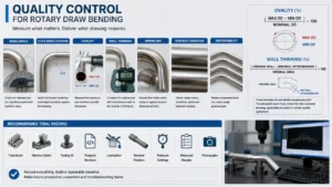
Quality validation should measure the dimensions and defects that matter to the customer drawing. Typical checks include cut length, bend angle, bend position, straight length, tube-end position, end-form dimensions, 3D centerline profile, ovality, wall thinning, wrinkles, cracks, scratches, dents, burrs, and surface quality.
Useful measurement formulas
Ovality: (Dmax − Dmin) ÷ Dnominal × 100%
Wall thinning: (t0 − tmin) ÷ t0 × 100%
For example, a tube with a nominal OD of 38 mm, measured maximum OD of 38.30 mm, and measured minimum OD of 37.616 mm has approximately 1.8% ovality using the formula above. A tube with an initial wall thickness of 1.500 mm and a minimum formed wall thickness of 1.407 mm has approximately 6.2% wall thinning. These are calculation examples, not universal acceptance limits.
Sample and production validation
Sample trials should confirm both part quality and repeatability. A useful validation sequence is initial trial, parameter adjustment, sample confirmation, repeatability verification, and continuous-run testing.
One project-specific production record used an 8-hour run with 1,200 planned pieces, 1,185 actual pieces, 1,182 good pieces, and 3 non-conforming pieces. The resulting first-pass yield was 99.75%, while the planned-quantity completion rate was 98.75%. Because this record is project-specific, it should be used as a validation example rather than a general production promise.
For a new project, define the test duration, sample quantity, cycle-time method, downtime treatment, inspection method, acceptance limits, and responsibility for recording results. Zhuoran’s sample service can be discussed when the drawing and material information are available.
How Should You Choose a Tube-Processing Equipment Supplier?
Choose a supplier that can connect the part drawing to the machine, tooling, automation, testing, and after-sales scope. A maximum tube diameter by itself is not enough to select equipment.
- Ask the supplier to review the 2D drawing or 3D model.
- Confirm material, OD, wall thickness, CLR, bend sequence, and end features.
- Separate standard machine functions from optional automation.
- Request a tooling list with included and excluded items.
- Define sample bending, dimensional inspection, and acceptance requirements.
- Compare cycle time using the same part, loading method, and inspection method.
- Confirm installation, training, spare parts, warranty, delivery, and Incoterms in the quotation.
This approach prevents a low machine price from hiding missing tooling, manual handling, additional inspection equipment, or later integration costs.
Zhuoran’s Role in Exhaust Tube Processing
Zhuoran Machinery supplies tube-processing equipment for operations such as CNC tube bending, pipe cutting, and tube end forming. For automotive tube applications, the equipment configuration can be evaluated from the tube drawing, material, geometry, production volume, and required quality checks.
Depending on the project, CNC equipment can be combined into a larger processing line. Automatic feeding, cutting, unloading, robotic handling, inline inspection, NG sorting, and line control are not assumed to be included in every quotation. They must be confirmed against the part and production requirements.
For a practical recommendation, send the tube material and grade, OD, wall thickness, blank length, CLR, bend angles, bend count, rotation angles, end-forming details, annual volume, target cycle time, inspection requirements, and available drawing files.
Exhaust Tube Manufacturing RFQ Checklist
Include the following information in an RFQ:
- 2D drawing and 3D STEP file
- Material grade, condition, coating, and applicable standard
- Tube OD, wall thickness, and incoming tolerance
- Blank length and cutting tolerance
- CLR, bend angles, bend count, bend sequence, and rotation angles
- Datum definition and straight-length requirements
- End expansion, reduction, flare, bead, notch, or other end-form details
- Surface requirements, burr limits, and prohibited defects
- Annual volume, batch size, shifts, and target cycle time
- Required tooling, mandrel, wiper die, pressure die, and multi-stack tooling
- Automatic feeding, cutting, unloading, inspection, robotics, or line-control requirements
- Sample quantity, FAT/SAT, inspection method, and final acceptance criteria
- Installation, training, warranty, spare parts, delivery, and packaging requirements
If you are planning an exhaust tube project, send Zhuoran the drawing, material, OD, wall thickness, CLR, bend schedule, end-forming requirements, production target, and inspection criteria. The engineering team can then recommend a suitable tube-processing configuration and identify which items require sample testing or project-specific automation design.
Common Questions About Exhaust Tube Manufacturing
What is the first step in manufacturing an exhaust tube?
Start with the part drawing and material data. Confirm the tube OD, wall thickness, CLR, bend schedule, end features, tolerances, and production target before selecting equipment.
Are exhaust tubes always bent with a mandrel?
No. A mandrel is selected when the tube geometry, material, wall thickness, CLR, and quality requirements justify internal support. The need should be confirmed by tooling review and trial bending.
Can one machine complete the whole exhaust system?
Usually not. A tube bender prepares bent tube components. Cutting, end forming, welding, inspection, leak testing, assembly, and emissions-related validation may require separate equipment or integrated line modules.
What materials can be used for exhaust tubes?
Common choices include stainless steels, coated or aluminized steels, and other application-specific grades. The exact grade should be selected from temperature, corrosion, forming, joining, cost, and customer requirements.
How do I compare exhaust tube machine quotations?
Compare the complete scope: machine, controls, tooling, automation, sample trials, inspection, installation, training, warranty, delivery, and acceptance testing. Do not compare only the base machine price.
What should I send to Zhuoran for a recommendation?
Send the part drawing or STEP file, material grade, OD, wall thickness, CLR, bend schedule, end-forming details, production volume, target cycle time, quality requirements, and automation expectations.
Technical References and Source Notes
The following references support the process, material, manufacturing, and regulatory context of this guide:
- U.S. EPA Vehicle Testing Regulations
- U.S. EPA Vehicle and Engine Certification
- Nippon Steel technical report on automotive exhaust materials
- Production Process of an Automotive Exhaust
- AM Exhaust manufacturing and quality process
- Auto-Jet OEM exhaust manufacturing overview
These sources provide general industry and regulatory context. They do not replace the customer drawing, material certificate, sample trial, inspection plan, or signed technical agreement for a specific project.