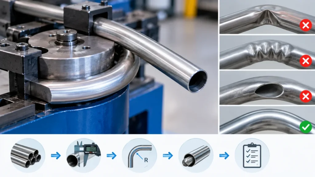
To bend a thin wall tube without kinking, match the bending tool to the tube, choose a suitable bend radius, and assess whether the wall needs internal support. Start with the material grade, outside diameter, wall thickness, and required bend geometry. Then make a trial bend and inspect it before committing more material.
A thin wall tube can flatten or wrinkle even when the equipment has enough force to bend it. This guide focuses on round metal tubing and explains how to evaluate the method, investigate defects, and check the finished part.
Why Does a Thin Wall Tube Kink During Bending?
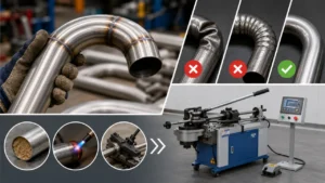
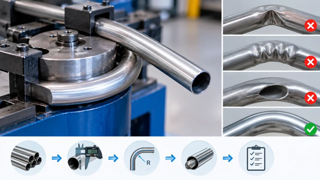
During bending, the outer side of the tube stretches while the inner side compresses. With insufficient support for the material and bend geometry, the cross-section can flatten and the inner wall can buckle. EAA describes this progression in its explanation of what happens when tubing bends.
Before adjusting the process, identify what you see:
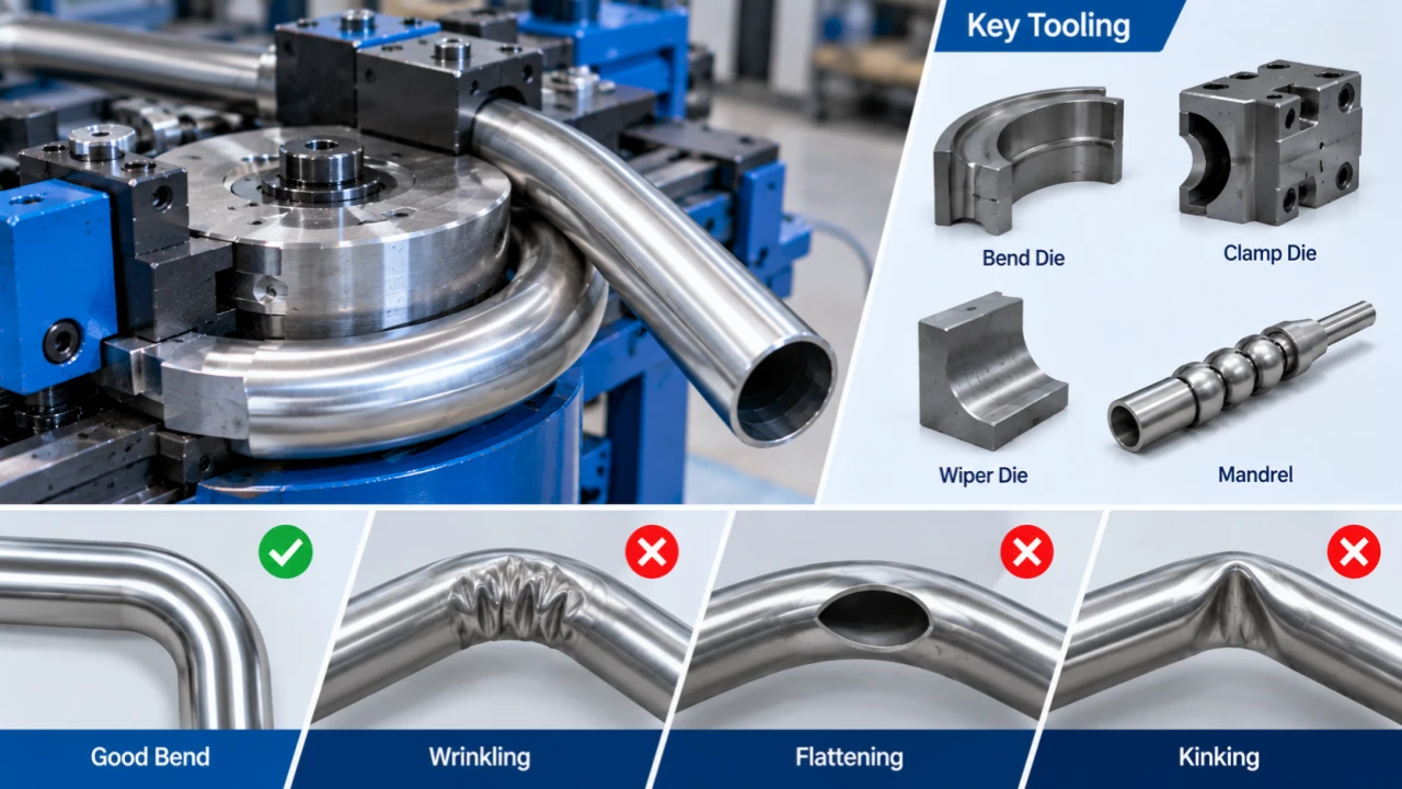
- Kinking: a concentrated fold or collapse that interrupts the curve.
- Wrinkling: ripples or folds along the inside of the bend.
- Flattening or ovality: distortion of the round cross-section.
- Cracking: a visible opening or fracture that requires separate investigation.
Photograph the defect from the side and along the tube. Mark whether it starts near the beginning, middle, or end of the bend. Include a photograph of the tooling arrangement.
These observations give the tooling supplier more useful information than “the tube will not bend.” Avoid treating every defect as proof that you need a larger machine.
Thin Wall Tube Dimensions to Check Before Bending
For a thin wall tube bending job, specify the material condition as well as the dimensions. Use the following checklist to describe the part before choosing equipment.
| Information | What to record |
|---|---|
| Material | Grade and supplied condition, including temper or heat treatment where relevant |
| Outside diameter | Nominal OD and any available measured variation |
| Wall thickness | Nominal thickness and available material tolerances |
| Bend geometry | Centerline radius, angle, straight lengths, and orientation between bends |
| Part requirements | Drawing tolerances, surface requirements, and inspection criteria |
| Production needs | Prototype quantity, batch size, and expected repeat orders |
Ask for clarification if the drawing labels a radius without identifying its reference. Keep the centerline radius separate from the inside or outside radius in your calculations and supplier correspondence.
For multiple bends, send the complete drawing. A description of one bend does not communicate the straight lengths and orientations of the finished part.
Calculate Wall Factor and Relative Bend Radius
Two useful starting calculations are:
Wall factor = outside diameter ÷ wall thickness
Relative bend radius = centerline radius ÷ outside diameter
OMNI-X uses both ratios in its mandrel and wiper die selection guide. It describes the chart as a basic guide and recommends further consultation because other factors influence tooling selection.
Consider this hypothetical thin wall tube specification. The values illustrate the calculation, not a proven production setup:
| Parameter | Value |
|---|---|
| Outside diameter | 30 mm |
| Wall thickness | 0.75 mm |
| Centerline radius | 45 mm |
| Wall factor | 30 ÷ 0.75 = 40 |
| Relative bend radius | 45 ÷ 30 = 1.5 |
Use consistent units. These ratios describe the geometry; they do not establish material suitability or guarantee an acceptable bend.
For a supplier discussion, attach the material grade, bend angle, drawing, and acceptance requirements to the calculation. Do not order tooling from the ratios alone.
Choose the Right Thin Wall Tube Bending Method
Choose a thin wall tube bender by checking its documented material, wall thickness, and radius range. Review the proposed tooling alongside the machine specification.
A machine listing the correct maximum diameter does not, by itself, establish suitability for your part. Ask which tube condition and tool set the manufacturer used to establish the stated capability.
Use the following comparison to organize the evaluation:
| Candidate approach | Basis for considering it | What to confirm before proceeding |
|---|---|---|
| Hand or bench bender with matching tooling | The manufacturer documents a suitable tube and radius combination | Material condition, tooling size, wall range, and required finished quality |
| Rotary draw bending without a mandrel | The tooling supplier considers unsupported bending suitable for the application | Trial results for section distortion and the drawing requirements |
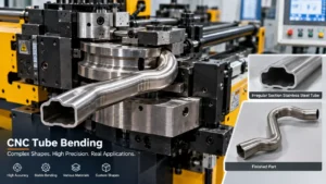
| Rotary draw bending with a mandrel | The application requires support inside the tube during forming | Mandrel configuration, fit, settings, and compatible external tooling |
| Specialist process review | Available equipment cannot demonstrate the required result | Whether to change tooling, the process, or the design with engineering approval |
Swagelok’s bench top bender manual illustrates why equipment-specific instructions matter. It provides tube data and explains the importance of matching bend shoes, rollers, radius, and forming pressure.
Apply those instructions to the equipment they describe. Do not transfer roller adjustments from a bench bender to a different machine configuration.
Does Your Thin Wall Tube Need a Mandrel?
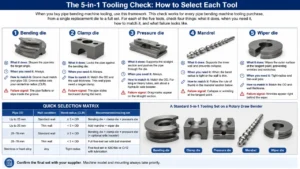
In rotary draw bending, a mandrel supports a thin wall tube internally. A wiper die provides support at the inside of the bend to help control wrinkling. They perform different functions within the tooling arrangement.
A plug mandrel provides solid internal support at the bend. For more demanding combinations of thin walls and tight radii, evaluate a ball mandrel, whose linked segments support the tube farther around the curve. The required configuration depends on the application.
Check the external tools too. The bend die forms the radius, the clamp die grips the tube, and the pressure die supports it during forming. A wiper die helps control inner-radius wrinkling. Adding a mandrel does not correct an unsuitable or worn external tool set. See Unison’s rotary draw tooling guide for the tool functions.
Bend Tooling identifies diameter, wall thickness, centerline radius, bend angle, and material as factors in determining whether a mandrel or wiper is needed. Its guidance also distinguishes applications that need a mandrel from those that need both tools.
Set Up and Test the Bend
For a thin wall tube trial, identify each sample and save the initial setup before changing it. Use the machine manufacturer’s operating procedure and keep hands clear of moving tooling.
1. Check the sample material
Use a thin wall tube sample that represents the intended production material. Record the grade and condition from the available material documents. Inspect the bend area for existing dents or surface damage and note any uncertainty about the stock.
2. Confirm the tool set
Record the bend die radius and tooling identifiers. Check the installation against the supplier’s instructions before bending. For a compound part, confirm the planned bend sequence with the operator or supplier.
3. Establish the specified support settings
Start from the settings supplied for the tooling. OMNI-X advises using its recommended mandrel settings, observing the first bend, and making adjustments based on the result. Its mandrel setup guidance also warns that incorrect positioning can damage the tube or tooling.
For your thin wall tube setup, use the toolmaker’s starting position and a documented reference point. An offset taken from another job may refer to different tooling or geometry.
4. Confirm lubrication and cleaning requirements
Select lubricant with the tooling supplier, including where to apply it and how to remove it. OMNI-X identifies tube material, production volume, downstream processing, and end use as factors in lubricant selection.
Include cleaning requirements in the discussion if the tube will undergo further processing or carry a specified medium.
5. Make and identify the trial part
Label the thin wall tube sample and record the setup. After unloading, check its shape and released angle before changing settings. Photograph any defect and note its position along the bend.
6. Plan the next trial
Write down the reason for each adjustment. Where practical, change one factor at a time so you can compare the result. If the supplier requires coordinated adjustments, record them together.
Troubleshoot Kinks, Wrinkles, and Flattening
Diagnose thin wall tube bending defects by checking the measured tube, installed tooling, and documented settings together. Use the table to choose what to inspect first; follow the equipment instructions for actual adjustments.
| Observation | First checks | Next action | What to compare |
|---|---|---|---|
| Local fold or collapse | Compare the measured tube OD with the tooling specification; check the selected radius and support arrangement | Correct a tooling mismatch or have the toolmaker reassess support for the specified bend | Defect location and cross-section measurements |
| Ripples on the inner bend | Check the specified wiper arrangement, tool condition, and setup against the tooling instructions | Restore the specified setup before testing further changes | Ripple location and extent |
| Flattened cross-section | Check tool fit and, on a mandrel setup, the specified mandrel position | Return to the documented setup; evaluate adjustments through trial parts | Measurements at the same locations on each sample |
| Crack or split | Material identification, surface condition, and setup record | Stop trial production and seek engineering or supplier review | Results of an agreed corrective trial and inspection |
| Tool marks | Tool condition, cleanliness, and specified contact settings | Review the affected contact area and permitted adjustments | Surface condition against the drawing requirement |
| Released angle differs from target | Measurement method and springback compensation | Follow the equipment’s compensation procedure | Angle after unloading |
Keep the failed samples until the investigation ends. Numbered parts and setup records make comparisons easier.
For example, “sample B has fewer inner ripples but still exceeds the agreed section requirement” gives a more precise basis for the next decision than “sample B looks better.”
Do not keep adjusting a process without a defined acceptance target. Ask the responsible engineer to clarify the drawing if the team cannot agree on what constitutes an acceptable result.
Inspect the Finished Thin Wall Tube Bend
Inspect each trial thin wall tube against the agreed drawing requirements. Record where and how you measured it so that later samples can be compared on the same basis.
A practical inspection plan can address:
- Appearance: visible folds, wrinkles, cracks, dents, and tool marks.
- Geometry: released angle, bend position, straight lengths, and orientation.
- Cross-section: diameter variation at agreed locations around the bend.
- Wall thickness: measurements where the application requires them.
- Assembly: fit against the drawing, fixture, or mating components.
These are proposed inspection categories. The responsible engineer should determine the required checks and acceptance limits for the application.
If you report ovality as a percentage, state the calculation and reference diameter. Record the measured diameters as well, so another person can understand the result without guessing which convention you used.
Wall thickness requires a suitable measurement method. Evident describes ultrasonic measurement of small-diameter tubing and states that operators should select the instrument and transducer configuration after testing product samples. Its tube wall thickness application note supports evaluating ultrasonic gauging, not assuming any handheld gauge can measure any bend.
For a curved region, confirm access, geometry, material, and thickness range with the inspection specialist. Agree on an alternative method if the proposed setup cannot produce reliable measurements.
Record Results for Repeat Jobs
Create a thin wall tube bending record that another operator can use to identify the material, tools, settings, and acceptance requirements:
| Record | Suggested contents |
|---|---|
| Material | Grade, supplied condition, batch identification, and dimensions |
| Tooling | Die identifiers, radius, and support configuration |
| Setup | Machine program or settings and relevant adjustments |
| Inspection | Measurement locations, method, results, and acceptance criteria |
| Outcome | Accepted, rejected, or awaiting further evaluation |
One acceptable sample provides evidence for that sample. Before claiming repeatability, agree on a trial quantity and evaluate the resulting parts.
Keep changes to material, tooling, or settings visible in the record. This gives the production team a starting point when a later batch behaves differently.
Questions About Bending Thin-Wall Tubing
Can you bend a thin-wall tube without a mandrel?
You can bend a thin wall tube without a mandrel in some applications. Assess the material, diameter, wall thickness, bend radius, angle, and required quality against the tooling supplier’s guidance. Confirm the result through a trial. The description “thin wall” alone does not establish whether unsupported bending will meet your requirements.
Does filling tubing with sand prevent kinking?
Sand can support a thin-wall tube in some manual bending applications; the EAA article discusses this method. It does not establish that filling will meet your dimensional or cleanliness requirements. For production work, ask how the supplier will validate the result and remove the filler. Do not assume that a filled tube will tolerate any chosen radius.
Is there a minimum bend radius for thin-wall tubing?
Use a radius recommendation tied to the material, dimensions, process, and tooling. A ratio from a selection chart is a starting point for that chart’s application, not a universal minimum. If your drawing requires a tighter radius than the available process can demonstrate, discuss tooling options or an approved design change.
Should thin-wall tubing be heated before bending?
Do not add heating to a cold-bending procedure without an approved material and process specification. Establish the grade and supplied condition first, then ask the responsible engineer whether a thermal process is suitable. The description “thin wall tube” provides too little information to prescribe a heating temperature or procedure.
Why is the angle different after unloading?
The tube can spring back after the bending load is removed. Swagelok notes that springback varies with tube size, wall thickness, and material in its electric bender manual. Measure the released angle and use the equipment’s compensation procedure. Do not assume another job’s correction will produce the same result.
What to Send a Bending Supplier
For a thin wall tube bending quotation, send the complete drawing and the material specifications listed above. Add the order quantity, acceptance requirements, and photographs of any existing defects. Identify the current machine and tooling if you want help with an established process.
Ask the supplier to state the proposed tooling, trial conditions, and inspection method in the quotation. For repeat production, agree on how the trial will demonstrate consistency across multiple parts.