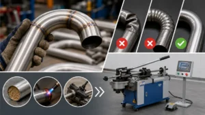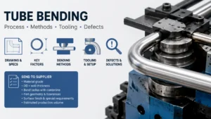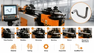
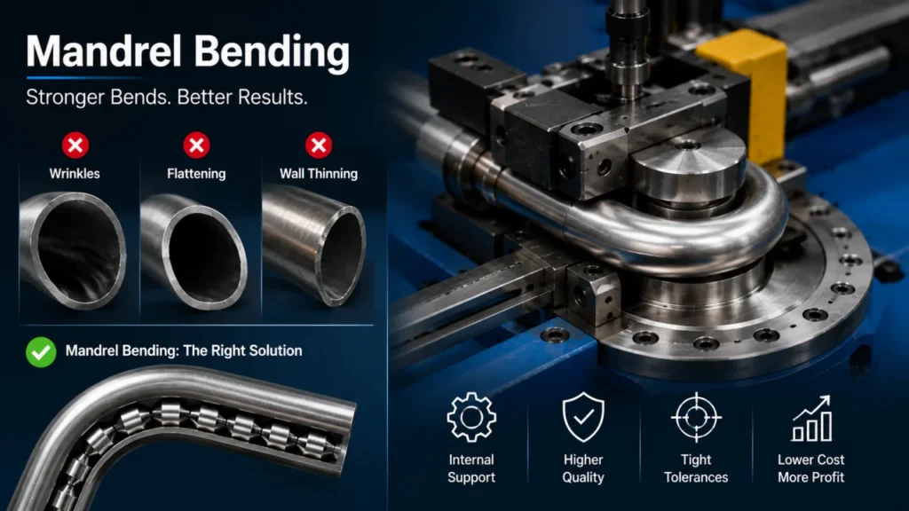
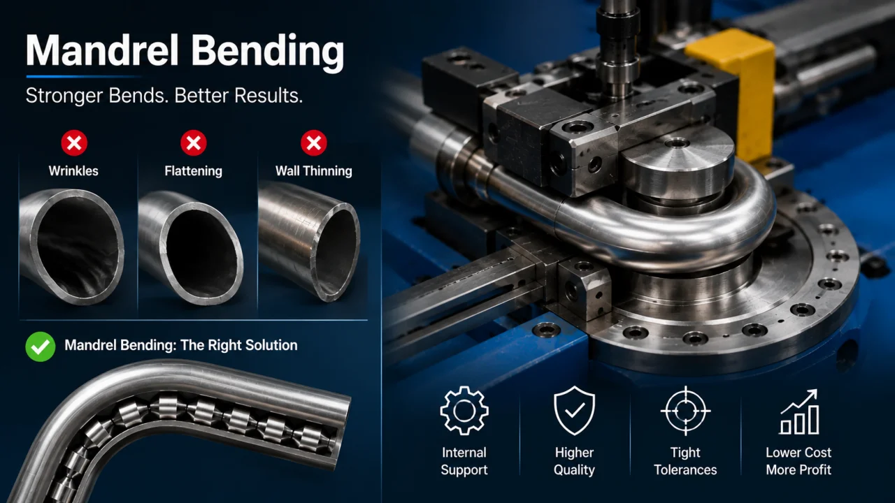
If your bent tubes come out with inner-wall wrinkles, flattened cross-sections, or excessive wall thinning, you are not alone. These defects rank among the most frequent quality complaints in tube fabrication, and they cost your shop real money in scrap, rework, and rejected deliveries. Mandrel bending offers a systematic, mechanics-based solution rather than a band-aid fix. In this guide, you will learn exactly how internal support works, what quality standards you should apply, how to choose the right mandrel for your application, and how to avoid the most costly mistakes.
What Is Mandrel Bending and Why Does It Matter?
The Core Principle: Internal Support at the Point of Bend
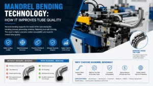
Mandrel tube bending is a specialized form of rotary draw bending where a solid or articulated support rod — the mandrel — is inserted into the tube interior during forming. In mandrel tube bending, the mandrel stays positioned at the tangent point, the exact location where the tube transitions from straight to curved, providing internal reinforcement precisely where compressive and tensile forces peak.
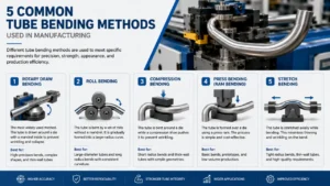
Without internal support, your tube wall has nothing to resist deformation from within. Consequently, the material buckles, flattens, or stretches uncontrollably. This process changes the load path: the interior wall receives direct mechanical backing, and the cross-section holds its roundness far more effectively. This principle separates mandrel bending from other methods like press bending or crush bending, which rely solely on external force and accept significant distortion as a trade-off.
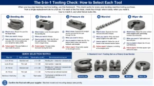
The 5 Tooling Components That Control Bend Quality
A complete mandrel tube bending setup uses five distinct tooling components, and each one controls a specific category of defect. You need to understand all five because they work as a system:
| Component | Primary Function | Defect It Controls |
|---|---|---|
| Bend die | Forms your tube’s outer radius | Extrados shape, bend radius accuracy |
| Clamp die | Grips your tube firmly against the bend die | Slippage, loss of tangent control |
| Pressure die | Applies lateral force to feed your tube | Inadequate feeding, buckling |
| Mandrel | Supports your interior wall at the tangent | Wrinkling, ovality, collapse |
| Wiper die | Supports your tube just past the tangent | Inner-wall wrinkling at the back of the bend |
Understanding what each component does matters because many shops treat the mandrel as a cure-all while neglecting the wiper die or pressure die settings. In practice, the process succeeds only when all five components work as a system. If you misconfigure one, the others cannot fully compensate.
The 5 Tube Quality Defects Mandrel Bending Solves
Wrinkling — The Inner Wall Buckles Under Compression
Wrinkling occurs on the intrados (the inner radius of your bend) where the tube wall experiences heavy compressive stress. When your material is thin relative to the tube diameter, the compressive force exceeds the wall’s buckling resistance, and the surface folds into a series of waves or ridges. Mandrel bending prevents this failure mode.
You will see this defect most often when bending thin-walled stainless steel tube at a tight centerline radius (CLR) — for example, a 1.5D bend on an automotive exhaust pipe with a wall factor above 40. The wrinkles restrict your fluid flow, create stress concentration points, and fail visual inspection immediately.
Ovality — The Cross-Section Flattens Into an Ellipse
Ovality, also called flattening, happens when your tube cross-section deforms from a perfect circle into an elliptical shape. The bending process naturally pulls the top and bottom of your tube inward because nothing inside the tube resists it — and this is precisely the deformation that mandrel tube bending targets.
You can calculate ovality using this formula:
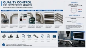
Ovality % = ((D_max − D_min) / D_nom) × 100Where D_max is the maximum measured diameter, D_min is the minimum, and D_nom is the nominal outside diameter. Acceptable ovality depends on your application — a structural handrail tolerates more than a hydraulic pressure line — but the underlying mechanism is always the same: insufficient internal support at your point of bend. Internal mandrel support is the standard countermeasure.
Wall Thinning — The Outer Radius Stretches Too Far
On the extrados (the outer radius), your tube wall undergoes tensile stress. The material stretches as it wraps around the bend die, and your wall becomes thinner. You can estimate the minimum wall thickness after bending with this engineering formula:
t_min = t_nom × (R / (R + 0.5 × D))Where t_nom is your nominal wall thickness, R is the centerline radius, and D is your tube OD. For instance, if you bend a 50mm OD tube with 2mm wall at R = 100mm, your predicted minimum wall is approximately 1.6mm — a 20% reduction. Without the controlled support that mandrel bending provides, your actual thinning can far exceed this prediction, pushing your tube below acceptable limits.
Collapse and Cracking — When Thin Walls Give Up
Collapse, sometimes called kinking, is the catastrophic version of wrinkling and ovality combined. Your tube wall folds inward sharply, often creating a crease that you cannot rework. In extreme cases, micro-cracking appears at the extrados where tensile stress peaks, particularly with work-hardening materials like stainless steel 304. Once a crack initiates, your part is scrap.
This defect appears most frequently on thin-walled tube (wall factor > 50) bent at a radius tighter than 1.5D — precisely where mandrel tube bending matters most — or when operators use excessive machine force to compensate for inadequate tooling.
Springback — The Bend Angle Refuses to Stay
In the process, springback refers to the elastic recovery of your tube material after the bending force is released. Your tube springs open slightly, so the actual bend angle is less than your programmed angle. Typical springback values you can expect by material:
| Material | Springback (degrees) |
|---|---|
| Carbon steel | 1 – 3° |
| Stainless steel | 3 – 8° |
| Aluminum | 2 – 4° |
| Copper | 1 – 2° |
Springback is not a defect that mandrel bending eliminates. However, CNC mandrel benders with a springback compensation database can automatically over-bend by the predicted recovery angle, delivering finished angles within ±0.1° of specification. Without CNC compensation, mandrel tube bending still relies on trial-and-error, wasting material and time.
How the Mandrel Fixes Each Defect: Mechanics Explained
Blocking Wrinkles With Mandrel Balls and Wiper Die Teamwork
In the process, the mandrel prevents wrinkling by occupying the interior space at the tangent point, leaving no room for the wall to buckle inward. On thin-walled work, a multi-ball mandrel with articulated segments follows your curvature, and each ball supports a discrete section of the intrados. Meanwhile, the wiper die applies a counterforce just past the tangent, preventing your material from bunching up as it exits the bend zone. This teamwork is why, in mandrel bending, you must always evaluate mandrel and wiper die together — removing the wiper die while running a mandrel still allows back-end wrinkling.
Holding Roundness: How Internal Support Limits Ovality
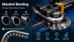
Mandrel tube bending places a rigid or semi-rigid core inside your tube to resist the flattening force. The result is dramatic: mandrel-bent tubes typically achieve ovality below 2–3%, while non-mandrel methods produce 8–15% ovality depending on wall thickness and radius. For pressure systems, this difference directly determines whether your part passes or fails ASME acceptance criteria.
Managing Wall Thinning: Support, Boost, and Speed Control
In the process, internal support does not magically prevent wall thinning — your extrados still stretches. However, internal support reduces the severity by distributing stress more evenly around your cross-section. Additionally, modern CNC machines apply boost pressure through the pressure die, feeding material into your bend zone rather than letting it stretch freely. Combined with controlled bend speed, these factors keep your wall thinning within the predictable range of the t_min formula rather than allowing uncontrolled reduction.
Preventing Collapse on Tight-Radius, Thin-Walled Work
For mandrel bending at 1D to 1.5D radius on thin-walled tube, a multi-ball mandrel with three to five articulated balls provides sequential support along the entire curvature. Each ball contacts the intrados at a different point along the arc, preventing wall collapse at any single location. This is why automotive exhaust manufacturers — who routinely bend 40–60mm OD tubes with 1–1.5mm walls at 1.5D — rely on multi-ball mandrels as standard practice.
Why Springback Still Needs CNC Compensation
Being honest here: mandrel tube bending does not eliminate springback. The elastic recovery of material happens regardless of internal support. What makes the difference is a CNC control system with a material-specific springback database. Your machine calculates the required over-bend angle based on material type, wall thickness, bend radius, and bend angle, then automatically adjusts. This is a critical selection criterion when evaluating mandrel-bending equipment — the control system matters as much as mechanical tooling.
| Defect | Without Mandrel | With Mandrel | Measurable Improvement |
|---|---|---|---|
| Wrinkling | Common, severe | Eliminated or minimal | Wrinkle height: >1.5% NPS → near 0 |
| Ovality | 8–15% | 2–3% | 4–5× reduction |
| Wall thinning | 22–28% | ≤7% | 3× reduction |
| Collapse | Frequent on tight radius | Rare | Defect rate: 15–30% → <2% |
| Springback | Unpredictable | Still present, but CNC-compensated | Angle tolerance: ±2° → ±0.1° |
How Good Is Good Enough? Quality Standards and Acceptance Limits
ASME B31.3 Acceptance Limits for Bent Tube and Pipe
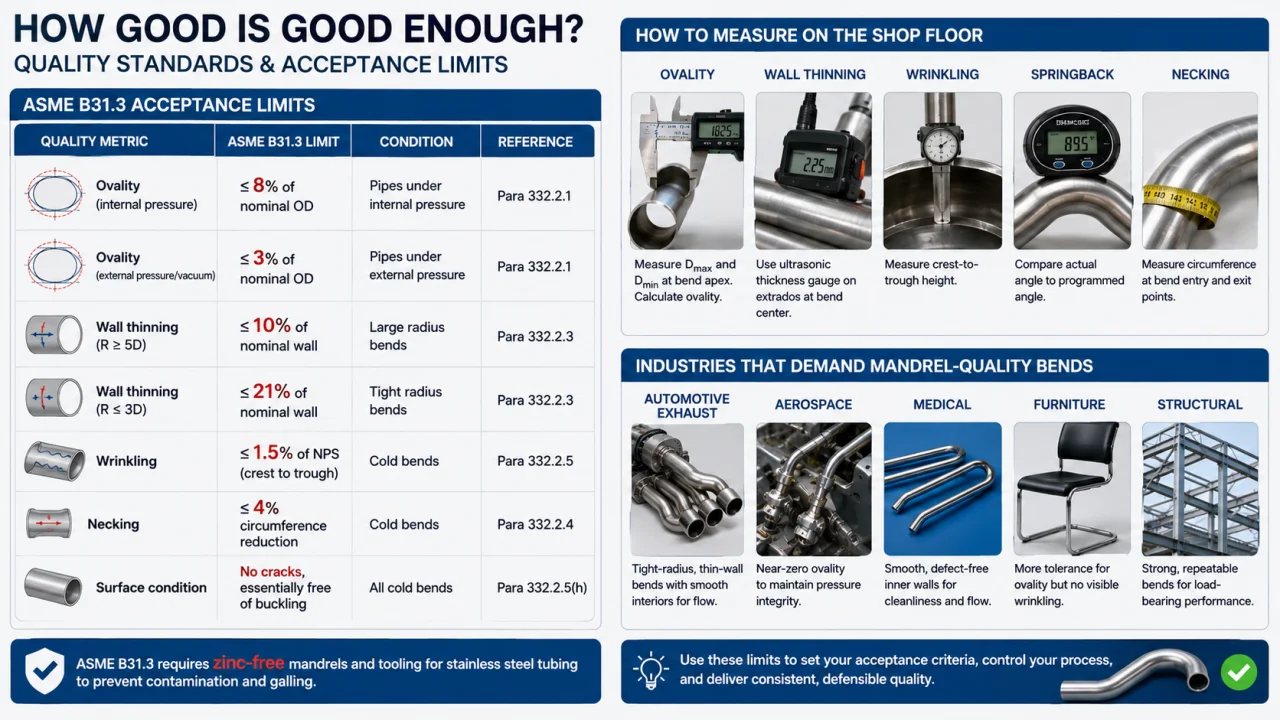
When you deliver bent tubes to a customer, “looks good” is not a quality standard. The most widely referenced acceptance criteria for mandrel bending come from ASME B31.3 (Process Piping), which specifies measurable limits for each defect type. These limits define what good mandrel tube bending quality looks like:
| Quality Metric | ASME B31.3 Limit | Condition | Reference |
|---|---|---|---|
| Ovality (internal pressure) | ≤ 8% of nominal OD | Pipes under internal pressure | Para 332.2.1 |
| Ovality (external pressure/vacuum) | ≤ 3% of nominal OD | Pipes under external pressure | Para 332.2.1 |
| Wall thinning (R ≥ 5D) | ≤ 10% of nominal wall | Large radius bends | Para 332.2.3 |
| Wall thinning (R ≤ 3D) | ≤ 21% of nominal wall | Tight radius bends | Para 332.2.3 |
| Wrinkling | ≤ 1.5% of NPS (crest to trough) | Cold bends | Para 332.2.5 |
| Necking | ≤ 4% circumference reduction | Cold bends | Para 332.2.4 |
| Surface condition | No cracks, essentially free of buckling | All cold bends | Para 332.2.5(h) |
These numbers give your bend results a concrete pass/fail benchmark. If a customer asks to verify bend quality, you can point to the exact paragraph and limit. Furthermore, for stainless steel tubing, ASME B31.3 requires that mandrels and tooling be zinc-free to prevent contamination and galling — a detail many shops overlook until corrosion issues appear months later.
How to Measure Each Quality Metric on the Shop Floor
Knowing the limits is only half the equation. You also need to measure your mandrel bending output correctly on the shop floor:
- Ovality: Use a caliper or micrometer to measure D_max and D_min at your bend apex. Calculate using the formula above.
- Wall thinning: Use an ultrasonic thickness gauge on your extrados at the bend center. This is faster and more accurate than cutting a sample section.
- Wrinkling: Measure crest-to-trough height with a depth gauge or profile tracer. Visual inspection catches severe cases, but the 1.5% NPS limit requires measurement.
- Springback: Compare your programmed angle to the actual angle using a digital protractor or your machine’s encoder feedback.
- Necking: Measure the circumference at your bend entry and exit points; compare to the nominal.
Industry Specifications That Demand Mandrel-Quality Bends
Different industries apply different pressure on bend quality. In automotive exhaust systems, mandrel tube bending is essentially mandatory — the work demands tight-radius, thin-walled bends with smooth interiors for optimal flow. Aerospace hydraulic lines demand near-zero ovality to maintain pressure integrity. Medical tubing requires smooth, defect-free inner walls for cleanliness and flow. Furniture and structural applications tolerate more ovality but still reject visible wrinkling. Understanding which specification a customer follows helps justify the process — or determine when it is unnecessary.
Choosing the Right Mandrel: The WF × DR Selection Matrix
Two Numbers That Decide Everything: Wall Factor and D-Ratio
Correct mandrel selection in mandrel bending starts with two calculations. First, the Wall Factor (WF):
Wall Factor = OD / Wall ThicknessA 50mm OD tube with 2mm wall gives you WF = 25. A 60mm OD tube with 1.5mm wall gives you WF = 40. Higher WF means thinner wall relative to your diameter — and a stronger case for mandrel tube bending support.
Second, the D-Ratio (DR), sometimes called the bend ratio:
D-Ratio = CLR / ODA 50mm OD tube bent at CLR = 75mm gives you DR = 1.5. A 50mm tube bent at CLR = 100mm gives you DR = 2.0. Lower DR means tighter radius — and greater deformation forces on your tube.
The 2-Axis Selection Matrix (With Real Examples)
By combining WF and DR, you can make a confident mandrel selection for any tube-bending job without guesswork. Here is your practical reference matrix:
| Wall Factor | D-Ratio | Recommended Mandrel | Example Scenario |
|---|---|---|---|
| < 20 (thick wall) | ≥ 2.0D | No mandrel needed | 38mm × 3mm steel, R = 100mm — structural tube |
| 20 – 40 (medium wall) | 1.5D – 2.5D | Plug or Form mandrel | 50mm × 2mm steel, R = 80mm — general industrial |
| > 40 (thin wall) | < 1.5D | Single ball mandrel | 60mm × 1.5mm stainless, R = 90mm — hydraulic line |
| > 40 + tight radius | < 1.5D + multi-bend | Multi-ball (3–5 balls) | 51mm × 1.2mm stainless, R = 76mm — exhaust system |
| Extreme: WF > 60 | < 1.0D | Flexible cable mandrel | 45mm × 0.8mm Inconel, R = 45mm — racing exhaust |
5 Mandrel Types Compared: Plug, Form, Ball, Multi-Ball, Flexible
| Type | Structure | Support Level | Min R/D | Best For |
|---|---|---|---|---|
| Solid plug | Single rigid cylinder | Low | ≥ 3D | Thick-wall structural tube |
| Form mandrel | Shaped to match bend contour | Medium | 2D – 3D | Medium-wall industrial tube |
| Single ball | One articulated ball on a rod | Medium | 2D | Hydraulic, cooling lines |
| Multi-ball | 3–5 articulated balls in series | High | 1D – 1.5D | Exhaust, thin-wall stainless |
| Flexible cable | Cable-linked segments | Very high | 0.8D – 1D | Ultra-thin, special alloys |
For multi-ball mandrels used in mandrel bending, you can estimate the number of balls your application needs:
n ≈ θ / (P / R), where P (ball pitch) typically ranges 1.0–1.2DFor a 180° bend at R = 75mm with P = 60mm, you need approximately 3 balls. Most mandrel tube bending applications for exhaust systems use 3–5 ball mandrels.
Material Matters: Stainless, Aluminum, Titanium, Copper
Material behavior also refines every mandrel selection, because each material responds differently under bending stress. Stainless steel work-hardens during bending, increasing your springback (3–8°) and requiring CNC compensation. It also galls easily, so you need zinc-free lubricant and polished mandrel surfaces. Aluminum bends more easily but has a narrow window between acceptable deformation and cracking. Titanium is highly springy and requires over-bend of 5–10° with careful speed control. Copper is soft with low springback but deforms easily, requiring careful pressure-die adjustment. Always factor material properties into your mandrel and tooling selection — the WF × DR matrix gives you the starting point, and material behavior fine-tunes your choice. For a deeper look at the broader rotary draw bending process, you can refer to this overview of tube bending fundamentals.
7 Costly Mandrel Bending Mistakes and How to Avoid Them
1. Mandrel Positioned Too Far Ahead
Symptom: Your tube wall thins excessively at the extrados, or the mandrel wedges into the bend and jams.
Root cause: The mandrel nose is positioned too far past your tangent point, creating excessive interference.
Correction: Pull your mandrel back so the ball centerline sits at or just before the tangent. Use the formula e = (1/3 to 2/3) × D as a starting reference for your mandrel bending setup, then fine-tune with test bends.
Prevention: Always verify your mandrel position with a test bend and wall-thickness measurement before production runs.
2. Mandrel Positioned Too Far Back
Symptom: Wrinkling appears on your intrados despite using a mandrel.
Root cause: Your mandrel sits behind the tangent point, leaving the critical deformation zone unsupported.
Correction: Advance your mandrel incrementally (0.5mm steps) until wrinkling disappears. Stop advancing once your wall thinning begins to exceed predictions.
Prevention: Document the optimal mandrel position per tube size and store it in your CNC program — repeatable mandrel tube bending depends on this discipline.
3. Wrong Clearance Between Mandrel and Tube ID
Symptom: Either galling/scratching on your tube interior (clearance too tight) or persistent ovality and wrinkling (clearance too loose).
Root cause: Your mandrel diameter does not match the tube ID properly. The optimal clearance is 0.15–0.25mm — tight enough to support, loose enough to allow your lubrication flow.
Correction: Measure the actual tube ID (not nominal) and select a mandrel 0.15–0.25mm smaller. Remember that your tube ID varies with wall-thickness tolerance.
Prevention: Include mandrel-to-tube clearance in your setup checklist for every new tube specification.
4. Skipping or Skimping on Lubrication
Symptom: Galling, material pickup on your mandrel, or tube interior scratches — especially on stainless steel.
Root cause: Insufficient lubricant or wrong lubricant type. Stainless steel requires zinc-free lubricant to prevent contamination.
Correction: Apply lubricant generously to your mandrel before insertion. In mandrel bending, always use a lubricant rated for the material you are bending.
Prevention: Set up a mandrel tube bending lubrication procedure and never skip it to save time — galling damage ruins far more value than your lubricant costs.
5. Worn or Misaligned Wiper Die
Symptom: Wrinkling appears at the back of your bend (after the tangent) even though your mandrel is correctly positioned.
Root cause: Your wiper die is worn, improperly seated, or misaligned. In the process, the wiper die’s job is to hold your material flat just past the tangent — if it fails, your tube bunches and wrinkles.
Correction: Inspect your wiper die contact surface. If worn, replace it. Re-align so the wiper die contacts your tube evenly across its full width.
Prevention: Include wiper die inspection in your tooling setup checklist. Replace before wear becomes visible in your bend quality.
6. Ignoring Springback Compensation
Symptom: Your finished bend angle is consistently 2–5° less than programmed, requiring rework.
Root cause: Your CNC program does not include springback compensation, or the compensation value is outdated for your current material batch.
Correction: Perform a test bend, measure your actual angle, calculate springback, and enter the over-bend value into your CNC program. Modern mandrel bending machines with a springback database automate this for you.
Prevention: In mandrel tube bending, re-verify springback values whenever you change material batches — even same-spec stainless from different heats can vary by 1–2°.
7. Using Max Machine Force to Mask Bad Tooling
Symptom: Your machine is straining, your tube is marking, and quality is still marginal.
Root cause: Instead of fixing tooling issues (worn mandrel, wrong clearance, misaligned wiper die), your operator increases machine force to force the bend.
Correction: Stop and diagnose. Excessive force never fixes your tooling problem — it creates new ones like surface damage, mandrel breakage, and inconsistent results across your batches.
Prevention: Train your operators to recognize tooling problems versus force problems. In the process, if your machine needs more than 80% of rated force for a routine bend, something is wrong upstream.
Is Mandrel Bending Worth the Cost? A Practical ROI View
The Real Cost Structure: Machine, Tooling, Lubricant, Setup
A common question from shop owners is: “Mandrel bending costs more — is it justified for my shop?” Let us break down your real cost structure:
| Cost Category | Typical Range | Notes |
|---|---|---|
| CNC mandrel bending machine | $20,000 – $154,000+ | Depends on axis count, max tube size, control system |
| Mandrel tooling (mandrel + wiper die + clamp die) | $2,000 – $50,000+ | Depends on your tube size, mandrel type, material |
| Lubricant | $50 – $200/month | Zinc-free formulations cost more but are mandatory for stainless |
| Setup and programming time | 2 – 8 hours per new specification | Reduces with experience and good CNC programming |
| Annual maintenance | 8 – 12% of tooling cost | Wiper dies and mandrel balls are consumables |
Scrap Rate vs. Mandrel Investment: The Break-Even Logic
The real ROI calculation in mandrel tube bending is not about the cost of your mandrel tooling — it is about the cost of not using it. Here is a practical comparison you can use to justify your investment:
| Metric | Without Mandrel | With Mandrel |
|---|---|---|
| Scrap rate (thin-wall, tight radius) | 15 – 30% | 1 – 3% |
| Rework rate | 20 – 40% | 2 – 5% |
| Material cost per good part | High (includes scrapped material) | Low |
| Customer rejection rate | 10 – 25% | < 2% |
| Typical payback period for mandrel investment | — | 12 – 24 months |
Consider a shop running the process for 5,000 automotive exhaust tubes per year at $8 material cost each. At 20% scrap without mandrel, that is $8,000 in wasted material annually. A $5,000 mandrel tooling package pays for itself in your material savings alone within 7–8 months — before counting your rework labor, customer rejection costs, and delivery delays. You can learn more about rotary draw tube bending parameters from industry resources.
When You Don’t Need a Mandrel (Be Honest)
Being honest builds trust. You do not need a mandrel when:
- Your wall factor is below 20 (thick-wall tube)
- Your D-ratio is above 3D (very large radius)
- Your application tolerates ovality above 8% (non-pressurized structural parts)
- Your tube material is thick and ductile (e.g., carbon steel schedule 40)
In these cases, mandrel tooling adds cost to your setup without measurable quality benefit. A reputable equipment manufacturer will tell you this openly rather than upselling unnecessary configuration. For everything else — thin walls, tight radii, pressure applications, aesthetic requirements — mandrel bending is not optional for you. It is the difference between a part that passes your inspection and a part that costs you a customer.
What to Look for in a CNC Mandrel Bending Machine
Control System Features That Protect Tube Quality
In mandrel tube bending, your machine’s control system is as important as its mechanical tooling. Features that directly impact your bend quality include:
- Springback compensation database: Stores material-specific over-bend values that keep bend results repeatable
- 3D simulation: Lets you verify your bend program, mandrel position, and tooling interference before running material
- Automatic collision detection: Prevents your machine from executing a program that would damage tooling or your tube
- Multi-program storage: A PLC system like the one in Zhuoran’s DW series CNC benders stores up to 500 programs with 30 bends each, enabling rapid changeover between your part numbers
- Multi-language interface: Critical for your international production teams
- Remote editing: Allows your off-site process engineers to adjust programs without standing at the machine
Machine Capability Checklist Before You Buy
Before you invest in a mandrel bending machine, verify these capabilities against your actual production needs:
| Checklist Item | Why It Matters |
|---|---|
| Maximum tube OD and wall thickness | Must cover your full product range with margin |
| Number of axes (2/3/4/5/6) | More axes = more complex bend geometry, but higher cost |
| Mandrel extraction system | Automatic extraction saves your cycle time and prevents mandrel jamming |
| Bend radius range | Must reach your tightest required CLR |
| Feed length (Y-axis travel) | Determines your maximum overall tube length |
| Control system brand and features | Determines your long-term usability and support availability |
| Core component quality | Look for Schneider, NSK, Mitsubishi, Omron, Siemens — these determine your machine longevity |
The DW series from Zhuoran Machinery covers mandrel tube bending applications from 38mm to 168mm OD across 2-axis to 6-axis configurations, with PLC control featuring 500-program storage and an industrial control system with 3D simulation and remote editing. For shops serving multiple industries — from automotive exhaust to furniture and medical equipment — this range eliminates your need for multiple machines.
Why Machine Selection Depends on Your Application
Different applications demand different machine configurations. Automotive exhaust shops need 2-axis or 3-axis machines with multi-ball mandrel capability and fast cycle times. Furniture manufacturers often need 4-axis or 5-axis machines for your complex multi-bend geometries. Hydraulic tube producers prioritize precision and repeatability over speed. Medical tubing requires cleanroom-compatible tooling and documentation. Matching your machine to your application — rather than buying the most axes available — is the key to your sound investment.
FAQ — Mandrel Bending Questions Answered
What is mandrel bending?
Mandrel bending is a rotary draw bending process that uses an internal support rod (the mandrel) inserted into your tube during bending. The mandrel prevents your tube wall from wrinkling, flattening, or collapsing at the bend point, producing smooth, dimensionally accurate bends — especially on your thin-walled and tight-radius work.
How does mandrel bending differ from rotary draw bending?
Mandrel tube bending is a subcategory of rotary draw bending. All mandrel-assisted bending uses the rotary draw principle (tube drawn around a stationary bend die), but not all rotary draw bending uses a mandrel. The mandrel is the additional internal support that distinguishes your two processes.
How does mandrel bending prevent deformation?
The mandrel occupies your tube interior at the tangent point, physically blocking your wall from buckling inward (wrinkling) and holding your cross-section round (preventing ovality). Multi-ball mandrels follow your curvature, providing sequential support along your entire bend arc.
When do I need a mandrel for tube bending?
You need a mandrel when your Wall Factor (OD ÷ wall thickness) exceeds 20, or when your D-ratio (CLR ÷ OD) is below 2.0. The tighter your radius and thinner your wall, the more essential the mandrel becomes. See our guide on when to use a tube mandrel for a detailed decision framework.
Which materials are suitable for mandrel bending?
All common tube materials — carbon steel, stainless steel, aluminum, copper, titanium, and alloys — are suitable. The key difference is that each material requires you to use specific lubrication (zinc-free for stainless), springback compensation values, and sometimes specialized mandrel surface treatments.
Can mandrel bending handle tight-radius bends?
Yes. Multi-ball mandrels routinely handle your bends at 1D to 1.5D radius on thin-walled tube. For extreme cases (below 1D radius on ultra-thin wall), flexible cable mandrels provide the articulation you need. Tight-radius bends are where mandrel bending gives you the greatest quality advantage over other methods.
What types of mandrels are used in tube bending?
Five main types: solid plug, form mandrel, single ball, multi-ball (3–5 balls), and flexible cable. Your selection depends on Wall Factor, D-ratio, and material — use the WF × DR matrix to choose your right type.
How does mandrel bending ensure pipe integrity in bend tests?
By holding your ovality below 2–3%, wall thinning within 7%, and eliminating wrinkles, mandrel-bent tubes maintain your pressure integrity and pass hydrostatic and pneumatic tests at far higher rates than non-mandrel bends. ASME B31.3 acceptance limits are consistently met with your proper mandrel tooling.
How much does a mandrel bending machine cost?
CNC mandrel tube bending machines range from $20,000 for your entry-level 2-axis models to $154,000+ for 6-axis machines with advanced control systems. Tooling (mandrel, wiper die, clamp die) adds $2,000–$50,000 depending on your tube size and material. Your payback is typically 12–24 months through scrap reduction.
Mandrel vs non-mandrel bending: which is better?
It depends on your application. For thick-wall, large-radius, non-pressurized work, non-mandrel bending is adequate and more economical for you. For thin-wall, tight-radius, or pressurized applications, mandrel bending is essential — the quality difference is not marginal, it is the difference between your part passing and failing inspection.
Ready to Improve Your Tube Bending Quality?
Mandrel tube bending is a quality engineering decision that affects every tube you produce. By eliminating wrinkling, controlling ovality, managing wall thinning, and meeting ASME acceptance standards, the process reduces your scrap, satisfies your customers, and builds your reputation for consistent quality.
At Zhuoran Machinery, we have spent over a decade building CNC mandrel bending machines for customers across 80+ countries. Our DW series covers tube sizes from 38mm to 168mm, with PLC control, 3D simulation, and springback compensation built in. We offer you free sample bending, custom mandrel configurations, and remote technical support to help you get it right the first time.
Request a quote with your tube specifications, and our engineers will recommend the optimal machine and mandrel configuration for your application.