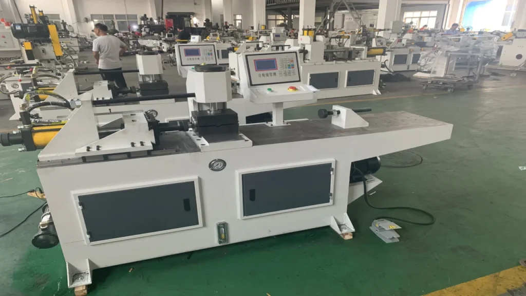
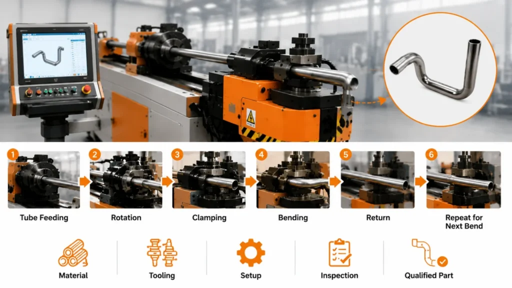
You can load a drawing into a control and still produce a poor tube. A CNC program controls motion, but your part also depends on the material, tooling, setup, and inspection method. If any of those inputs remain unclear, the machine may complete its cycle while the tube misses a critical dimension or surface requirement.
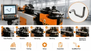
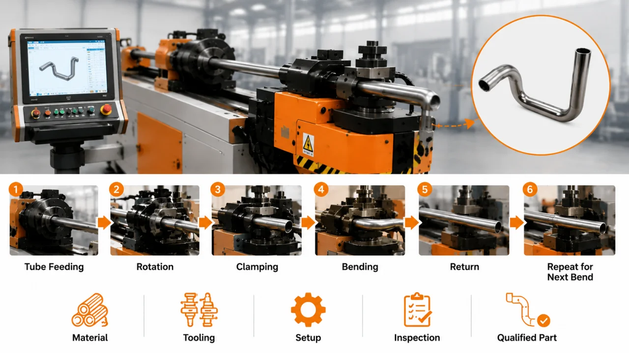
So, how does a CNC tube bender work in an industrial plant? The machine feeds the tube to a defined position, rotates it to the required plane, clamps it against the tooling, forms the bend, and repeats those actions for each bend in the program. Your team then checks the first part and adjusts the setup or compensation before releasing production.
This guide connects each machine action to the part geometry it creates. You will also see where tooling controls the material, where variation enters the process, and which project details you should confirm before you request a quotation.
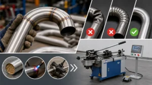
How does a CNC tube bender work? A CNC tube bender coordinates tube feeding, rotation, clamping, and bending through a programmed sequence. The program sets the motion, while the material, bend tooling, setup, and first-part inspection determine whether the finished tube meets your drawing.
What a CNC Tube Bender Controls
A CNC tube bender converts part geometry into coordinated mechanical actions. Four functions form the base of most cycles:
- Feed moves the tube to set a straight length or the distance between bends.
- Rotate turns the tube to set the next bend plane.
- Clamp and support hold the material against the tooling.
- Bend forms the tube around a bend die to create the target angle and centerline radius.
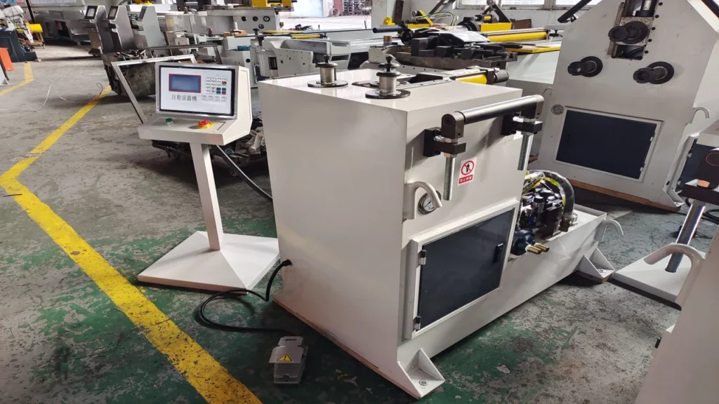
Your machine may add mandrel movement, pressure-die assistance, boosting, automatic loading, or unloading. Those functions depend on the machine and tooling configuration. The Zhuoran CNC pipe bending machine range includes different control and axis configurations, so you should match each quoted axis to a physical action.
Feed, Rotate, Clamp, and Bend
Feed distance affects the straight section before a bend and the spacing between bends. Rotation sets the orientation of the next bend in a three-dimensional part. Clamping transfers force without letting the tube slip, while the bending system drives the tube around the selected radius.
These motions need a shared reference. If the tube starts from a different position, slips during feeding, or rotates from the wrong datum, the program can repeat the wrong geometry with high consistency. Your drawing, datum scheme, and inspection plan must use compatible references.
Axis Names Vary Between Machine Builders
Manufacturers do not use one universal axis-naming system. Some controls describe axes with letters such as Y, B, and C. Others group actions by feed, rotation, bend, or auxiliary function. In practice, a higher axis count can indicate more controlled motion, but the number alone does not tell you which motion the machine performs.
Ask the supplier to map every quoted axis to its mechanical function. You should also confirm which functions come as standard equipment, which require options, and which depend on the selected controller. This check gives you a firmer basis for comparing two proposals that use different terminology.
How Does a CNC Tube Bender Work Through a Full Cycle?
A typical CNC tube bending cycle follows seven stages. Your part, tooling, and automation level may change the order or add extra operations.
1. Load the Tube and Set the Starting Reference
The operator or loading system places the tube in the machine. The machine then establishes a repeatable starting position before the first feed move.
Tube length, straightness, end condition, and material batch can affect this stage. A cut end with heavy burrs may disturb location or handling. A bent blank can also change how the tube enters a guide or clamp.
Before you approve the process, confirm the raw-material specification and allowed incoming condition. You should know whether the quoted scope assumes manual loading, a fixed stop, a sensor, or an automatic loading system.
2. Feed to the First Bend Position
The feed system advances the tube by a programmed distance. That move helps establish the first straight length and the position of the first bend relative to the chosen datum.
Feed accuracy alone cannot protect the part from tube slip or inconsistent blank length. Your team needs a measurement method that connects the drawing datum to the machine setup. For a multi-bend part, small differences at early bends can affect the final endpoint.
3. Rotate to the Required Bend Plane
The rotation system turns the tube before the next bend. This action creates the spatial relationship between bends and allows the machine to form a three-dimensional component.
Mirrored parts need extra attention. A left-hand and right-hand component may require a mirrored program, a changed loading direction, or another setup choice. Give the supplier both part drawings and identify how your team distinguishes the two parts during production and inspection.
4. Clamp and Support the Tube
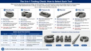
The clamp die holds the tube against the bend die. The pressure die supports the tube as the bend progresses. Depending on the geometry and quality requirement, the tooling set may also use a mandrel, wiper die, or other support components.
Tool contact can affect surface appearance. Insufficient restraint can allow slip or deformation. Too much force or a poor contact surface can leave marks. State your cosmetic and functional surface requirements in the RFQ instead of treating them as an inspection detail after delivery.
5. Form the Bend
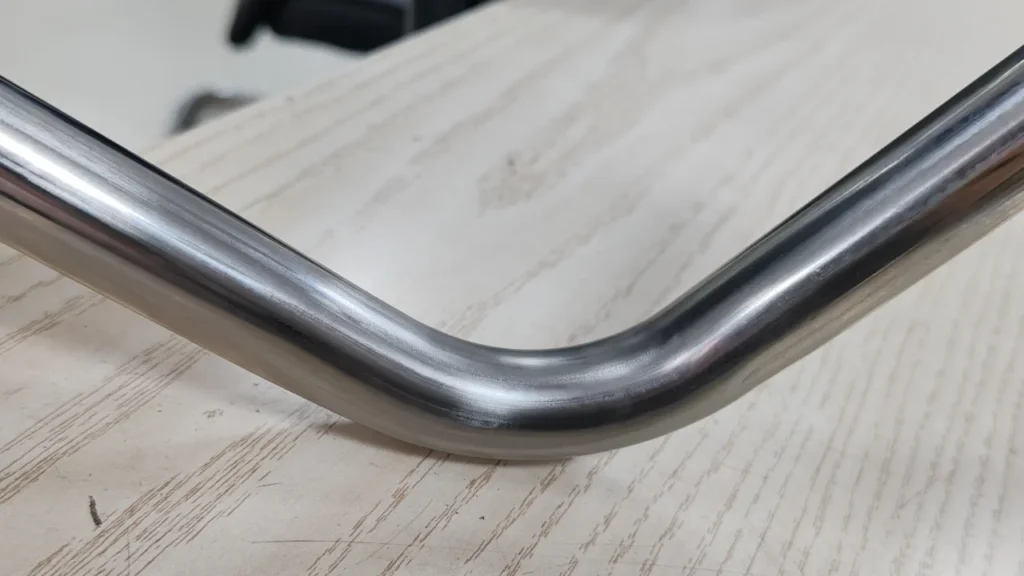
The bending mechanism rotates or moves the tooling to form the tube around the bend die. The material on the outside of the bend stretches, while material on the inside compresses. The combination of tube diameter, wall thickness, material, and centerline radius determines the forming challenge.
The tube also recovers part of its elastic deformation after the load drops. Engineers call this springback. Your team can use measured first-part results to adjust bend-angle compensation. A fixed springback percentage would give you a weak starting point because material and process conditions vary.
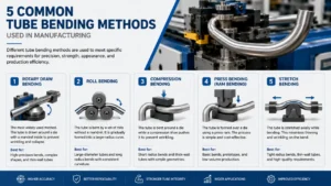
For a broader explanation of material deformation and bending methods, use a dedicated tube bending process guide rather than treating the machine cycle as a complete forming textbook. The SME training guide library also provides manufacturing training references for teams that need deeper process education.
6. Release, Reposition, and Repeat
After one bend, the machine releases the required tooling, feeds or rotates the tube, and prepares the next bend. It repeats this sequence until it completes the programmed geometry.
Part envelope and interference become important on complex components. A long leg can collide with the machine, tooling, or floor before the machine reaches the last bend. Program simulation can help your team identify a risk, but you still need to verify the actual tube, tooling, and machine layout.
The number of programmed bends does not prove that a machine can run the part. Ask the supplier to review the complete geometry, clamp length, bend sequence, and expected unloading method.
7. Unload and Inspect the First Part
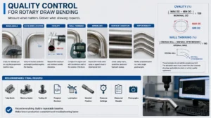
The machine or operator removes the finished tube. Your team then measures the first part against the agreed drawing features.
Choose the measurement method before commissioning. A tape measure cannot verify the same features as a checking fixture, arm, or coordinate measurement system. Identify critical dimensions, bend planes, endpoint positions, and surface criteria. The supplier and buyer should also use the same datum definitions.
The first-part result closes the control loop. Your engineer can adjust the program or setup from measured evidence, then document the accepted settings for repeat production.
| Machine action | What it sets on your part | Main tooling or system | Typical risk | What you should confirm |
|---|---|---|---|---|
| Feed | Straight length and bend position | Feed unit and gripping system | Slip or position variation | Drawing datum and feed verification |
| Rotate | Bend plane | Rotation unit and clamp | Plane or orientation error | 3D data and mirrored-part logic |
| Clamp and support | Material restraint | Clamp, pressure, and bend dies | Marks, slip, or local deformation | Tooling scope and surface requirement |
| Bend | Radius and angle | Bend die and support tooling | Springback, thinning, or flattening | Material, OD, wall thickness, and CLR |
| Inspect and compensate | Accepted first-part geometry | Agreed gauge or measurement system | Uncontrolled correction | Critical dimensions and acceptance method |
The Program Does Not Guarantee a Good Part
A CNC program gives the machine repeatable commands. Your process still needs stable input material, suitable tooling, a controlled setup, and a defined inspection method.
Material and Springback Change the Result
Two tubes with the same nominal dimensions can produce different bend results when their material condition, actual wall thickness, or mechanical properties vary. Those differences can change springback and deformation.
Set purchasing limits for the material characteristics that affect your part. If your application uses several suppliers or grades, tell the machine builder before tooling and acceptance planning. Your first-part procedure should use material that represents production stock.
Tooling Controls the Tube During Deformation
The bend die sets the bend radius and guides the tube path. The clamp die transfers force without slip. Engineers add a mandrel, wiper die, or another support component when the geometry and quality requirement call for it.
You should request a tooling list with the quotation. Confirm which dies the supplier includes, which change parts cover each tube size, and which surface treatment or insert applies to sensitive materials. The Unison overview of tube bending machines and Olicana’s guide to tube bending techniques and tools provide useful background, but your tooling decision still needs your part data.
Setup and First-Part Inspection Close the Loop
Your engineer sets tooling position, clamping force, support conditions, and program compensation. The team then measures the first part and records the accepted values.
This loop separates repeatable motion from controlled production. Without a shared inspection method, the buyer and supplier may judge the same sample in different ways. Put the critical dimensions, measurement tools, sample material, and acceptance conditions into the project record.
Controls and Automation Should Match Your Production
Control features can reduce programming work and help your team manage complex parts. Zhuoran’s product catalogue describes PLC-based graphical operation for some equipment and an industrial-controller option with STEP import, 3D simulation, remote editing, and interference detection. Confirm model compatibility and option status during quotation because a catalogue feature does not establish the configuration of every machine.
Program Creation and 3D Data
A controller that imports part data can reduce manual coordinate entry for complex geometries. Program storage also helps you return to recurring parts. Your team still needs to check the imported geometry, tooling assignment, bend sequence, and datum interpretation.
Ask for a programming demonstration based on one of your drawings. You will learn more from that test than from a list of controller features.
Interference Checks and Repeat Production
Simulation can flag a possible collision between the part, machine, and tooling. It cannot know every real-world condition unless the model includes the correct tooling and setup.
For repeat work, confirm how the control stores programs, corrections, tooling references, and operator instructions. Your changeover plan should also define who verifies the first part after a program recall.
Evaluate Automation Against the Production Pattern
For example, high-volume repeated parts may justify automatic loading, unloading, or in-process handling. Low-volume work with frequent part changes places more value on setup access, program management, and tooling change time.
| Your production condition | Configuration question to ask |
|---|---|
| Low volume with frequent part changes | How will your team change and verify programs and tooling? |
| Repeated complex 3D parts | How does the control handle 3D data, interference, and correction? |
| High-volume repeated parts | Which loading, unloading, and in-process checks does the cell require? |
| Several tube-processing operations | Which operations should remain separate, and which should share handling? |
Avoid choosing automation from an axis count or marketing label. Give the supplier your annual volume, batch size, changeover pattern, staffing plan, and target inspection method.
Bending Within a Tube-Processing Route
Industrial manufacturing routes often combine several tube operations. Your component may require cutting, deburring or chamfering, bending, end forming, and inspection. The drawing and assembly sequence determine which steps you need and when you run them.
Cutting and End Preparation Before Bending
Consistent blank length helps your team establish a stable machine reference. Burrs or damaged ends can affect handling, location, and later assembly. Review the available pipe cutting machines and pipe chamfering machines if your project needs controlled blank preparation.
A separate machine often gives a plant more routing flexibility. An integrated line can reduce handling for a stable, high-volume product. Your volume, changeover needs, floor space, and inspection plan should drive that decision.
End Forming and Inspection After Bending
Some parts need expansion, reduction, beading, or another end shape. Geometry and clamping access may require your team to form the end before or after bending. The tube end forming machine range provides a starting point for that discussion.
Mannesmann’s tube and pipe processing overview also illustrates how cutting, end preparation, bending, and related operations form a broader production route. Treat each operation as a separate process decision before you combine equipment into a line.
Information to Confirm Before You Request a Quote
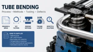
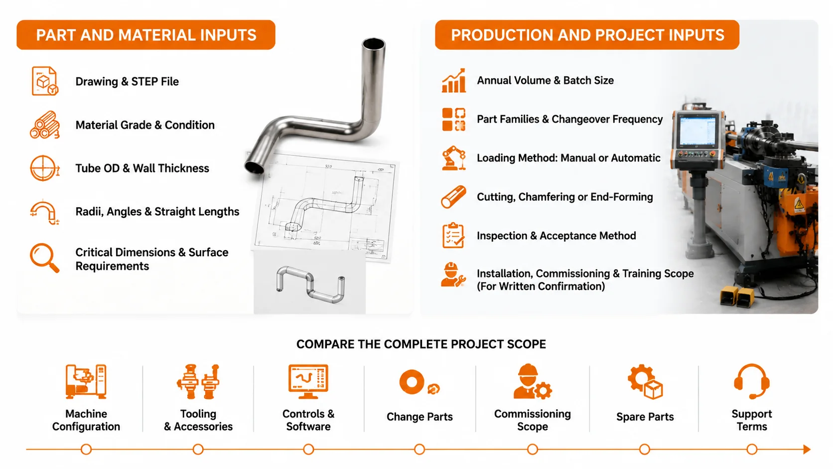
A useful quotation starts with the part, production plan, and acceptance method. Send the following information:
Part and Material Inputs
- A dimensioned drawing and STEP file, if available
- Material grade and supply condition
- Tube outside diameter and wall thickness
- Centerline radii, bend angles, and straight lengths
- Critical dimensions and surface requirements
Production and Project Inputs
- Expected annual volume and batch size
- Number of part families and changeover frequency
- Manual or automatic loading expectations
- Cutting, chamfering, or end-forming requirements
- Inspection and acceptance method
- Required installation, commissioning, and training scope for written confirmation
Compare the Complete Project Scope
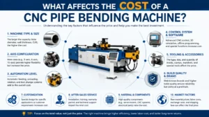
Machine capacity forms one part of the proposal. Compare the machine configuration, tooling, controls, change parts, commissioning scope, spare parts, and support terms.
If a supplier offers sample trials or acceptance testing, ask for the scope in writing. Define the sample material, drawing revision, measured features, inspection method, and acceptance responsibility. You can also review Zhuoran’s design and engineering service, sample service, and installation, commissioning, and training page before you confirm the commercial terms.
Frequently Asked Questions About CNC Tube Bending
How does a CNC tube bender work?
The controller converts bend data into coordinated feed, rotation, clamping, and bending commands. Tooling restrains the material during each bend, and your team uses first-part measurements to set any required compensation before releasing the job.
What do the axes on a CNC tube bender control?
The axes can control physical functions such as linear feeding, tube rotation, bending, and auxiliary tooling movement. Manufacturers use different axis names and control structures. Ask each supplier to map the quoted axes to mechanical actions, then confirm which functions come with the proposed machine.
Why does springback occur after tube bending?
The tube stores elastic strain while the tooling applies force. Part of that strain recovers when the load drops, so the final angle can differ from the loaded position. Material properties, geometry, and process conditions affect the result. Engineers use measured first-part data to set compensation.
Does every bent tube need a mandrel?
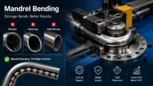
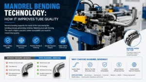
No. Your tooling engineer selects a mandrel based on the material, tube diameter, wall thickness, bend radius, and quality requirement. Some parts run without one. Tight radii, thin walls, or strict shape requirements may need internal or external support tooling.
What information do you need to select a CNC tube bender?
Provide the drawing, material, outside diameter, wall thickness, bend radii, angles, straight lengths, production volume, and critical quality requirements. Include related cutting or end-forming operations and your inspection method. These details help the supplier evaluate the machine and tooling as one project.
Send Your Tube Drawing for a Machine-and-Tooling Review
Your drawing gives an engineer a practical basis for reviewing bend geometry, machine motion, tooling, part handling, and related processing. Include the material, OD, wall thickness, CLR, expected volume, and critical dimensions with your request.
Send your tube drawing and project requirements,or compare the available CNC pipe bending machine configurations. Zhuoran can then discuss a machine-and-tooling proposal against the information you provide. Final capability, testing, and service terms should appear in the written quotation for your project.
Use the cycle, tooling, and inspection checks above when a project team asks, “How does a CNC tube bender work?” The useful answer connects machine motion to the accepted part and the written project scope.
References and Further Reading
- Zhuoran Machinery: Products
- Zhuoran Machinery: CNC Pipe Bending Machines
- Zhuoran Machinery: Design and Engineering
- Zhuoran Machinery: Installation, Commissioning and Training
- Zhuoran Machinery: After-Sales Service
- Zhuoran Machinery: Automotive Applications
- Zhuoran Machinery: Aerospace Applications
- SME Training Guides
- Mannesmann: Tube and Pipe Processing
- Unison: What Is a Tube Bending Machine?
- Olicana: Tube Bending Techniques, Tools and Applications
- AUTECH: How Does a CNC Tube Bender Work?