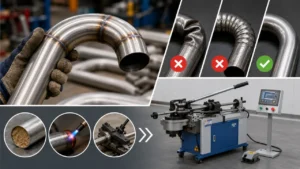
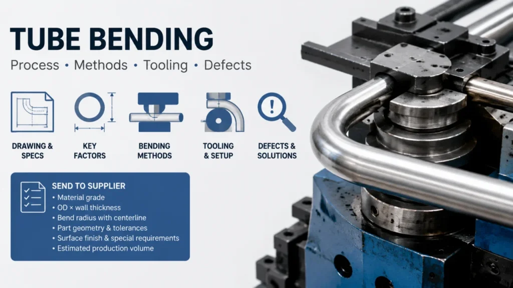
A tube can look acceptable after bending and still fail during assembly. The angle may be wrong, the cross-section may flatten, or the outside wall may become too thin. These problems often begin before the machine starts. The drawing may lack a centerline radius, the supplier may receive an incomplete material specification, or the chosen tube bending process may not suit the part.
You need more than a maximum tube diameter to select a tube bending process or machine. Outside diameter, wall thickness, material grade, bend radius, part geometry, surface requirements, tolerance, and production volume all influence the result. Tooling and setup then determine whether the tube holds its shape through the bend.
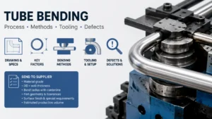
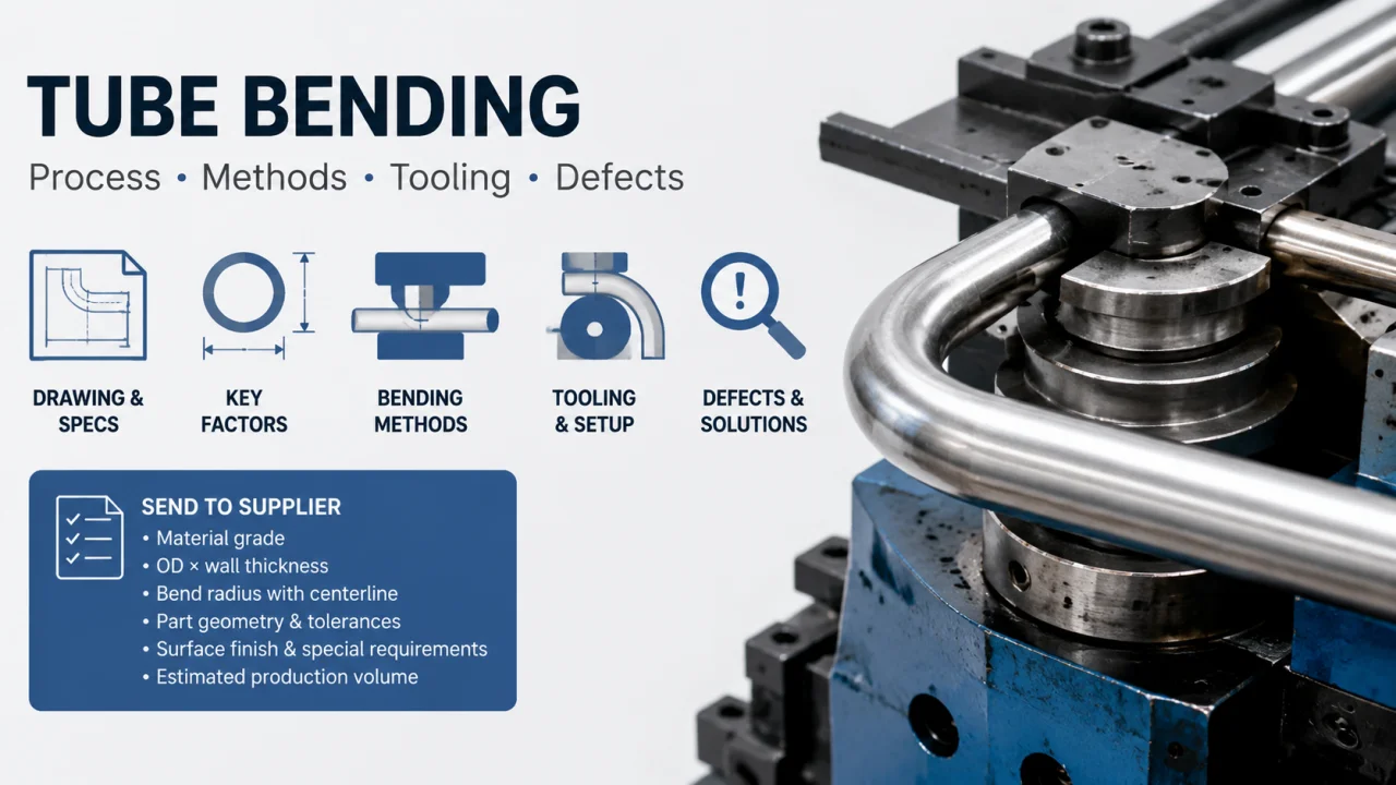
This guide explains how the tube bending process works, compares the main bending methods, and shows how tooling controls deformation. You will also learn how to diagnose common defects and what to send a supplier before requesting a machine recommendation or quotation.
How Does the Tube Bending Process Work?
The machine applies force around or against a forming tool until the tube takes the required shape. The bend places the outside wall under tension and compresses the inside wall. The neutral area between them sees less length change.
During the tube bending process, these forces do not remain balanced on their own. The outside wall can thin or crack. The inside wall can wrinkle.
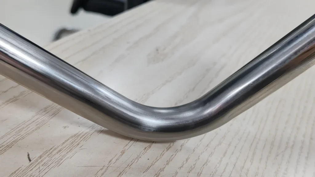
The tube cross-section can become oval or collapse. Material recovery after the force is removed can also change the final angle. Engineers call this recovery springback.
A review of tube bending research identifies wall thinning, wrinkling, cross-section distortion, and springback as core forming problems. The amount of deformation depends on the material, tube geometry, bend radius, friction, and tool support. See the academic review of tube bending technology for a technical treatment of these relationships.
Tension on the Outside and Compression on the Inside
The outer wall travels around a longer path than the tube centerline, so it stretches. The inner wall travels around a shorter path, so it compresses. A tight bend increases both effects.
A thin-wall tube gives the compressive force less material to stabilize. A high-strength material may resist forming and produce more springback. A softer grade may need less forming force, but a thin wall or tight radius can still require internal support. You must consider these behaviors before selecting tooling or setting machine capacity.
Why Material, Wall Thickness, and Bend Radius Matter
Outside diameter and wall thickness describe the tube geometry, but they do not describe the complete forming load. Material grade, heat treatment, weld seam condition, and surface finish can change the result.
Centerline radius, or CLR, measures the distance from the bend center to the tube centerline. A smaller CLR creates a tighter bend. Tight bends on thin-wall tube tend to need stronger cross-section support than large-radius bends on thick-wall tube.
Send the exact material grade rather than a broad label such as “stainless steel.” Also state whether the visible surface must remain free from clamp marks or scratches. The supplier needs this information to assess the tube bending process, tooling material, lubrication, and clamping method.
What Makes a Tube Bend Difficult?
Several part features increase tube bending process risk:
- a small CLR relative to the tube diameter;
- a thin wall relative to the outside diameter;
- short straight sections between bends;
- bends in several planes;
- high-strength or low-ductility material;
- strict ovality, wall-thinning, or surface limits.
You should treat these features as a combined problem. A small tube is not an easy part when it has a thin wall, tight radius, short clamp length, and several rotations.
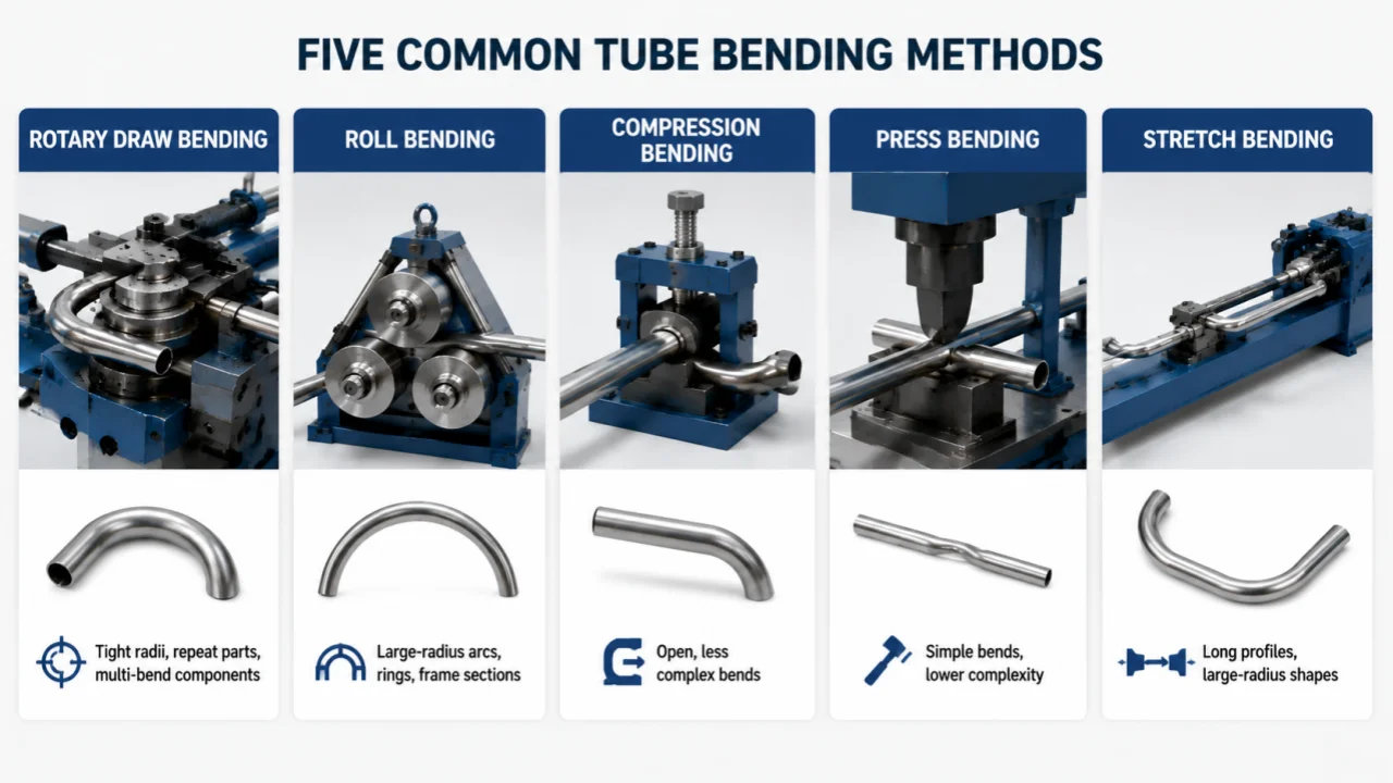
Five Common Tube Bending Methods Compared
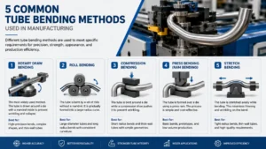
Manufacturers use several tube bending methods because no single method covers every geometry. The table below gives you a first-pass comparison.
| Method | Best suited to | Main strength | Main limitation |
|---|---|---|---|
| Rotary draw bending | Tight radii, repeat parts, multi-bend components | Strong control of bend geometry and tooling support | Requires matched tooling and careful setup |
| Roll bending | Large-radius arcs, rings, and frame sections | Forms broad curves through several passes | Does not suit a typical tight elbow |
| Compression bending | Open, less complex bends | Direct tube bending process with a limited tool set | Offers less control over tight-radius deformation |
| Press or ram bending | Simple bends where cross-section control is less strict | Low tube bending process complexity | Can flatten or distort the tube |
| Stretch bending | Long profiles and large-radius shapes | Tension helps control the profile during forming | Requires suitable gripping and dedicated equipment |
The Unison tube bending FAQs and the OMNI-X bending guide provide useful background on bending methods, tooling, and deformation control.
Rotary Draw Bending
Rotary draw bending clamps the tube to a bend die. The die rotates and draws the tube around a fixed radius. A pressure die supports the straight section while the tube moves into the bend.
This tube bending process suits parts with defined radii, repeated bends, and controlled orientation between bends. A wiper die and mandrel can support the tube when the geometry raises the risk of wrinkling or collapse.
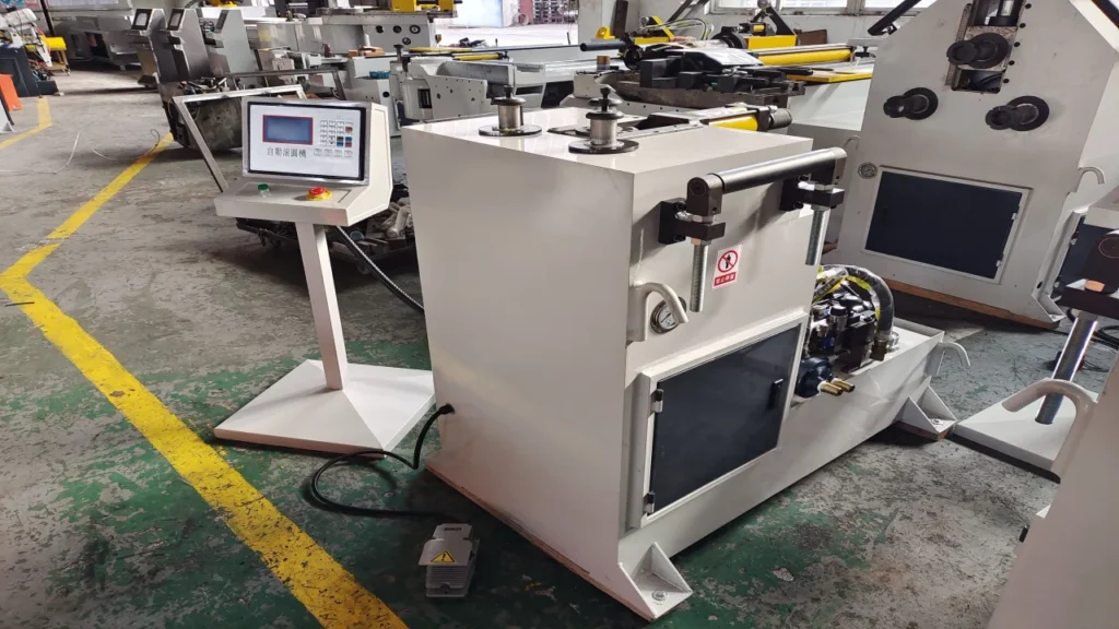
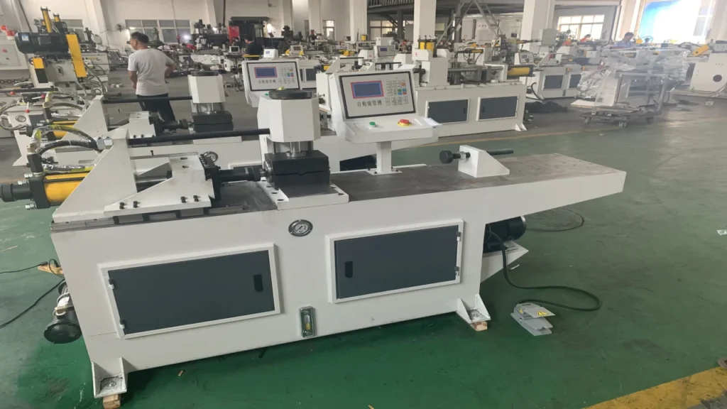
Rotary draw bending forms the basis of many CNC pipe bending machines and NC pipe bending machines. CNC and NC describe machine control. Rotary draw describes the forming method.
Roll Bending
Roll bending moves the tube through three or more rolls. The rolls apply pressure in stages, and repeated passes create a large-radius curve. This method works well for rings, arches, frames, and broad structural curves.
Choose roll bending when the drawing calls for a gradual radius rather than a tight elbow. A tube rolling machine addresses a different geometry from a rotary draw bender, even when both machines process the same tube size.
Compression and Press Bending
Compression bending holds one end and wipes the tube around a stationary form. It can suit simple bends with less demanding geometry. Press bending pushes the tube between supports with a ram or forming die.
Both methods can reduce tooling or machine complexity, but you should review cross-section requirements before choosing them. A part that must fit a mating assembly may need more deformation control than a structural bend with broad dimensional limits.
Stretch Bending
Stretch bending holds the profile under tension while wrapping it around a form. Manufacturers use it for long sections and large-radius components, including some architectural or aerospace profiles.
This method needs equipment and gripping systems designed for the part length and profile. It serves a different part family from rotary draw or roll bending and usually requires dedicated gripping and form tooling.
How to Choose the Right Tube Bending Process
Use seven inputs to narrow the tube bending process before comparing machine models. This approach prevents a common procurement error: selecting a machine from its advertised maximum diameter and discovering that it cannot produce the required part.
1. Tube Size and Wall Thickness
Provide the outside diameter and actual wall thickness. A nominal tube description may hide dimensional variation. The supplier must check whether the machine has enough bending and clamping capacity for your material and radius.
Wall thickness also affects the need for internal support. Thin-wall tube can buckle under compression or lose its cross-section under bending force.
2. Material and Formability
State the material standard or grade, tube construction, and heat condition. Carbon steel, stainless steel, aluminum, and copper respond to forming in different ways. Two grades from the same material family can also require different compensation or support.
If the tube has a weld seam, identify its location and consistency. If you use polished or coated tube, tell the supplier which surfaces remain visible after assembly.
3. Centerline Radius and Bend Angle
Provide the CLR from the drawing. Do not substitute the inside radius unless you label it. The supplier uses the CLR to design the bend die and assess deformation risk.
The bend angle affects material travel and springback compensation. A shallow bend and a near-return bend place different demands on tooling, clearance, and program setup.
4. Part Geometry and Number of Bends
Count the bends, then check the straight length and rotation between them. Short distances can limit clamp length or create tool interference. Multi-plane parts require controlled tube rotation or accurate fixtures.
A 3D file helps the engineer check collision risk and bend sequence. A clear 2D drawing should show dimensions, radii, angles, datums, and tolerances.
5. Dimensional and Surface Requirements
Specify the dimensions that affect assembly. These may include bend angle, leg length, hole position, overall envelope, and rotation between bends. State how you measure each tolerance.
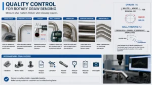
Also define acceptable ovality, wall thinning, wrinkles, and tool marks if these features affect function or appearance. The phrase “good bending quality” gives a supplier no acceptance target.
Surface requirements can change the tube bending process because polished, coated, or cosmetic parts may need protective tooling and controlled handling.
6. Production Volume
A workshop producing short batches may favor flexible setup and manual loading. A line producing one part family may need automatic loading, seam detection, unloading, or links to cutting and inspection equipment.
Provide annual volume, batch size, shifts, and expected product mix. Cycle time alone does not describe the production requirement because changeover and inspection can consume a large part of each shift.
Production volume also changes how you organize the tube bending process, including loading, unloading, inspection frequency, and changeover planning.
7. Required Automation Level
Automation should solve a production constraint in the tube bending process. CNC control helps with feeding, rotation, bend programming, and repeatable sequences. It cannot correct a poor tool design or an unsuitable tube bending process.
Use the part family and labor plan to decide which motions need control. The guide to CNC pipe bending machine cost explains how axis configuration, tooling, automation, and delivery scope affect a quotation.
If your drawing combines a tight CLR, thin wall, short straight lengths, or several rotations, send the part for technical review before comparing machine models. A drawing-led review gives you a more useful answer than a catalogue diameter alone.
| Your requirement | Tube bending process or equipment to evaluate first |
|---|---|
| Tight radii with several bends | Rotary draw bending with CNC or NC control |
| Large-radius frame or ring | Roll bending |
| Simple single bends in short batches | NC or a simpler bending system |
| Multi-plane parts with repeat production | CNC feeding and rotation |
| Mirrored left and right parts | Double-head or a dedicated production concept |
Tube Bending Tooling and What Each Tool Does
Tooling transfers machine force into the tube and supports the material during deformation. The tool set must match the outside diameter, radius, material, wall, and required surface.
Bend Die, Clamp Die, and Pressure Die
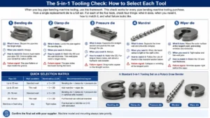
The bend die defines the CLR and supports the tube through the bend. The clamp die grips the tube against the bend die so the rotating tool can draw it around the radius. The pressure die supports the straight tube and guides it into the bend.
Grip length matters. A short straight section may not give the clamp die enough contact area. Excess clamping pressure can mark or deform the surface, while weak clamping can let the tube slip and change the bend location.
Wiper Die and Mandrel
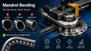
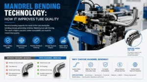
The wiper die supports the inside of the tube near the tangent point. It helps control wrinkles as the inner wall compresses. The mandrel supports the tube from inside and helps the cross-section resist collapse.
Mandrels can use different nose or ball arrangements. The correct design depends on the tube and bend. The OMNI-X bending guide explains how mandrel and wiper-die choices change with bend conditions and defect risk.
When Is Mandrel Tube Bending Required?
You should evaluate mandrel tube bending when the drawing combines a thin wall, tight CLR, strict ovality, or a visible surface that cannot tolerate collapse. The need depends on the complete geometry rather than a universal diameter-to-wall formula.
Ask the supplier to explain the proposed mandrel type, position, lubrication, and extraction sequence. Also ask whether the quotation includes the mandrel and wiper die. A machine offer without the required tools does not represent a production-ready package.
Step-by-Step Tube Bending Process
A controlled tube bending process starts with the drawing and ends with a validated production setup. The steps below apply to many rotary draw projects, though the exact sequence changes with the machine and part.
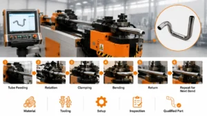
Step 1: Review the Drawing and Tube Specifications
The engineer checks the tube OD, wall, material, CLR, bend angles, straight lengths, rotations, tolerances, and surface requirements. The review should flag missing dimensions and areas where the tool may interfere with a previous bend.
Step 2: Select the Tube Bending Process and Machine
The engineer matches the part to rotary draw, roll, compression, press, or stretch bending. For a rotary draw part, the team then checks machine capacity, controlled axes, working length, tooling-stack needs, and loading method.
Step 3: Design and Install the Tooling
The tool designer sets the bend groove, clamp length, pressure-die contact, and any mandrel or wiper support. The setup technician aligns the tools and checks clearance through the full machine motion.
Step 4: Set the Program and Tube Bending Process Parameters
The operator enters feeding length, rotation, bend angle, speed, clamping sequence, mandrel position, and compensation values. Some CNC systems can import part data or display a simulation, but these functions depend on the selected control package.
Step 5: Produce a Trial Bend
The team runs a sample with the agreed tube and tool set. A substitute material can give a misleading result because strength, surface, and wall variation affect the bend.
Step 6: Inspect and Correct the Part
The inspector checks angle, straight lengths, rotations, overall geometry, cross-section, wall condition, and surface. The tube bending process engineer then adjusts tool position, pressure, speed, or compensation based on the measured defect.
Step 7: Validate the Tube Bending Process Setup
The team confirms the first article and records the accepted program, tool setup, and inspection method. Production validation should use the agreed part requirements rather than a generic machine accuracy claim. The Swagelok tube bender manual provides practical examples of bend layout, springback allowance, and troubleshooting, although industrial machines still require model-specific setup instructions.
Zhuoran’s installation, commissioning, and training service describes drawing-based program setup, trial production, dimensional checks, parameter adjustment, and operator handover. Its catalogue also lists control configurations with program storage, coordinate conversion, and simulation options. Availability depends on the machine and controller selected for the project.
Common Tube Bending Defects and How to Correct Them
Defects provide clues about the tube bending process. Measure the part before changing several settings at once. A single controlled adjustment gives you a clearer cause-and-effect record.
| Defect | Possible causes | First checks |
|---|---|---|
| Wrinkling | Inner-wall instability, poor support, tool position, excess compression | Wiper die, mandrel position, pressure, lubrication |
| Flattening or ovality | Tight radius, weak internal support, tool mismatch | Tube bending process choice, mandrel, bend die and pressure die |
| Springback | Material strength, heat condition, bend geometry | Actual angle, compensation, material consistency |
| Wall thinning | Excess outer-wall strain, tight radius, tool drag | CLR, material, tooling alignment, lubrication |
| Cracking | Low ductility, damaged surface, excessive strain | Material certificate, tube edge condition, radius |
| Scratches or clamp marks | Dirty tools, rough contact surface, excess grip pressure | Tool finish, cleaning, lubrication, clamping force |
The CRD guide to tube bending quality issues provides a practical overview of defect causes. Academic research also connects forming conditions with springback, wall variation, and cross-section distortion. See this study of tube bending methods and defects.
Wrinkling and Tube Collapse
Wrinkles form on the inside of the bend when compressed material loses stability. Check whether the wall and CLR need a wiper die or mandrel. Then review tool position, pressure-die force, and lubrication.
Collapse or excess ovality points to inadequate cross-section support or an unsuitable bend condition. A mandrel can help, but tool alignment and tube bending process choice still control the result.
Springback and Dimensional Error
Springback changes the angle after the tools release the tube. Measure the finished part, calculate the difference from the target, and adjust compensation from test results. Material batches can behave differently, so keep the material specification and inspection method consistent.
Length and rotation errors can come from tube slip, feeding calibration, datum choice, or program input. Do not treat all dimensional errors as springback.
Wall Thinning and Cracking
The outer wall becomes thinner as it stretches. A tight radius, excessive drag, poor lubrication, or a material with limited ductility can increase the strain. Cracks may also start at scratches or weld defects.
If wall thickness affects pressure rating or fatigue life, define the measurement location and acceptance limit on the drawing. The supplier should validate the part against that requirement.
Surface Scratches and Tool Marks
Visible marks can come from dirt, damaged tool surfaces, sliding contact, or high clamping force. Clean and inspect the tooling before changing the program. Protective films and polished tools may help with appearance parts, but they must remain compatible with grip and tube bending process stability.
CNC vs NC Tube Bending: What Changes in the Tube Bending Process?
Buyers often mix the tube bending process method, control type, and drive system. Keep these categories separate:
- rotary draw or roll bending describes how the tube forms;
- CNC or NC describes how the machine controls movement and programs;
- hydraulic or servo describes how a machine drives selected motions;
- mandrel bending describes an internal support arrangement.
When an NC Tube Bender Is Enough
An NC machine can suit simple parts when an operator can load, rotate, and position the tube between bends. It may offer a lower automation cost and a direct setup for short batches.
Check labor, positioning accuracy, product mix, and operator skill. A low machine price can lose value if manual handling creates variation or limits output.
When CNC Control Adds Value
CNC control adds value when your parts need programmed feeding, tube rotation, several bend angles, or repeat production. It can reduce manual positioning and store programs for product families.
The control system cannot rescue the wrong tube bending process, tool geometry, or material specification. Ask the supplier to map each controlled axis to a movement your parts need.
How to Inspect a Bent Tube
Inspection should reflect how the part functions in assembly. Agree on datums, measurement tools, sampling, and acceptance limits before machine approval.
Dimensional Inspection
Check bend angle, straight length, CLR where required, overall envelope, and rotation between bends. A coordinate measuring machine or checking fixture may suit complex parts. Simpler parts may use gauges, angle tools, and dimensional fixtures.
Cross-Section and Wall Inspection
Measure ovality or flattening at the specified section. Check the inside for wrinkles and the outside for thinning or cracks. Wall measurement may require an ultrasonic gauge or a cut sample, depending on the requirement.
Surface and Production Validation
Inspect clamp marks, scratches, coating damage, and contamination under agreed lighting or visual criteria. Then confirm that the tube bending process can repeat the accepted part across the required sample quantity.
The drawing or approved sample should control acceptance. A catalogue capacity value cannot replace part-level validation.
Information to Send a Tube Bending Machine Supplier
An effective RFQ lets the supplier assess the tube bending process, machine, tooling, and project scope. Send the following information:
- tube outside diameter and wall thickness;
- material grade and tube standard;
- 2D drawing and 3D file, if available;
- CLR, bend angles, straight lengths, and rotations;
- dimensional, ovality, wall, and surface requirements;
- annual volume, batch size, and shifts;
- loading, unloading, and line-integration needs;
- raw tube and finished sample availability;
- destination, electrical supply, and requested delivery scope.
Why Maximum Tube Diameter Is Not Enough
Two parts with the same outside diameter can need different machines. Wall thickness changes force. CLR changes deformation and tooling. Part length affects feeding stroke, while bend sequence affects interference and axis control.
Ask each supplier to confirm the complete part, not a catalogue diameter. Zhuoran’s design and engineering service can provide a technical route for drawing review and machine configuration.
Drawing Review and Sample Bending
A drawing review identifies missing dimensions, tube bending process risk, and tool-access limits before you place an order. A sample bend can then test the proposed tools and parameters with your material.
Use the sample service to confirm the required submission and testing scope. Also define who supplies raw tube and tooling, which dimensions the supplier will inspect, and how both parties will approve the sample.
After equipment delivery, operator training and parameter handover affect how fast your team reaches stable production. Review the supplier’s after-sales service as part of the purchase rather than after a fault occurs.
Frequently Asked Questions About the Tube Bending Process
What is the most accurate tube bending process?
Rotary draw bending offers strong control for tight-radius and multi-bend parts because matched tools support the tube around a defined bend die. Accuracy still depends on material consistency, tooling, setup, compensation, and inspection. Compare processes against your drawing instead of treating one method as the most accurate for every part.
What is the difference between rotary draw bending and roll bending?
Rotary draw bending pulls a clamped tube around a bend die with a fixed CLR. It suits defined bends and tighter radii. Roll bending passes the tube through rolls in stages to create a broad curve, ring, or arch. Your part radius and geometry determine which method fits.
When does tube bending require a mandrel?
Evaluate a mandrel when the part combines a thin wall, tight CLR, strict ovality, or high surface requirements. Material behavior and tool setup also affect the decision. Send the supplier your tube specification and drawing so the tooling engineer can assess the required internal support.
Why does a tube wrinkle on the inside of a bend?
The inside wall compresses during bending. It can lose stability when the bend is tight or the tool set gives too little support. Check the wiper die, mandrel position, pressure-die setting, lubrication, and material condition. Change one factor at a time and measure the result.
How can tube flattening be reduced?
Start by checking whether the tube bending process and CLR suit the tube geometry. Then review mandrel support, bend-die fit, pressure-die alignment, and lubrication. Thin walls and tight radii need more support. Define the permitted ovality before trial bending so the supplier has a measurable target.
What is springback in tube bending?
Springback is the elastic recovery that changes the angle after the tools release the tube. The amount depends on material, wall thickness, radius, and bend angle. Tube bending process engineers measure the finished part and adjust the programmed or mechanical compensation from trial-bend results.
Is CNC tube bending better than NC bending?
CNC control suits parts that need programmed feeding, rotation, several bends, or repeat production. NC equipment can suit simple parts and short batches with manual handling. The better choice depends on part geometry, labor, product mix, output, and budget. Both still need suitable tooling and a validated tube bending process setup.
What information is needed for a tube bending machine quotation?
Send tube OD, wall thickness, material grade, CLR, bend angles, straight lengths, rotations, tolerances, surface requirements, production volume, and a part drawing. State your automation and delivery needs. These inputs let the supplier quote the machine, tooling, testing, and service scope on the same basis.
Discuss Your Tube Bending Project With Zhuoran
Your part drawing should lead the equipment decision. Tube geometry, material, quality limits, and production volume determine the tube bending process and tool set. Machine capacity becomes useful after those requirements are clear.
Send Zhuoran Machinery your drawing, tube specification, expected volume, and acceptance requirements. An engineer can review the bend method, machine control, tooling, and sample-validation scope before preparing a recommendation.