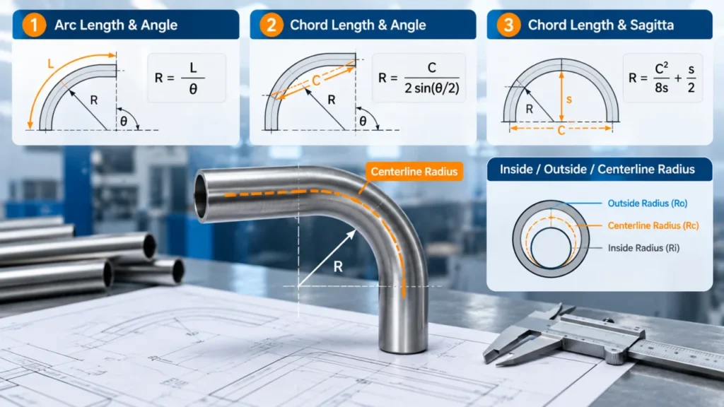
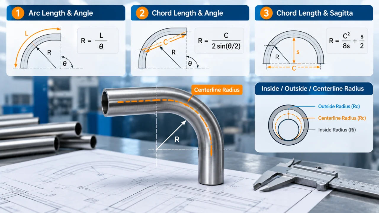
For a circular tube bend, calculate radius from arc length and angle, chord length and angle, or chord length and sagitta. If the drawing gives an inside or outside radius, use the tube outside diameter to convert it to centerline radius.
Before you start a bending radius calculation, identify the measurement path: a surface measurement and a centerline measurement describe different radii. The methods below apply to round metal tubing. They establish bend geometry; material and tooling checks determine whether you can produce the proposed bend.
Which Tube Bend Radius Are You Calculating?
Centerline Radius, Inside Radius, and Outside Radius
Centerline radius, or CLR, runs from the center of curvature to the tube centerline. Inside radius, Ri, reaches the tube’s inner side of the bend. Outside radius, Ro, reaches its outer side. These refer to the bend geometry; Ri does not mean the radius of the tube bore.
For an ideal round cross-section with concentric bend paths:
- CLR = Ri + OD/2
- CLR = Ro − OD/2
Here, OD means tube outside diameter. Bend Tooling’s formula reference gives the equivalent inside- and outside-radius relationships.
Label the intended radius on your drawing as CLR, inside radius, or outside radius. A supplier who receives only “R60” needs that reference to check your bending radius calculation and select tooling.
Choose a Formula from the Dimensions You Have
Use this table to choose a bending radius calculation method. In each formula, R belongs to the arc you measured. You can report the answer as CLR provided that those measurements describe the tube centerline.
| Known dimensions | Formula | Check before calculating |
|---|---|---|
| Arc length L and angle θ in radians | R = L/θ | L excludes straight sections |
| Arc length L and angle θ in degrees | R = 180L/(πθ) | θ is the angle swept by that arc |
| Chord c and sagitta h | R = c²/(8h) + h/2 | c and h describe the same circular path |
| Chord c and angle θ | R = c/[2sin(θ/2)] | Match the calculator’s angle mode to θ |
| Inside radius Ri and tube OD | CLR = Ri + OD/2 | The round-section assumption applies |
| Outside radius Ro and tube OD | CLR = Ro − OD/2 | The round-section assumption applies |
The arc and chord equations follow from the circular geometry documented in Wolfram MathWorld. Use positive lengths and a nonzero arc angle. The chord examples below cover arcs up to 180°; for larger arcs, define the measured segment before using the formula. All numerical examples are hypothetical teaching calculations.
You cannot complete a bending radius calculation from tube OD alone. For example, multiplying an OD of 25 mm by 2 gives a selected radius of 50 mm. You have selected a radius in that case, but you still need geometry to measure an existing bend and process evidence to establish whether the tube can withstand the operation.
Bending Radius Calculation Methods and Worked Examples
Bending Radius Calculation from Arc Length and Angle
For a circular arc, length equals radius multiplied by the angle in radians:
L = Rθ, so R = L/θ.
To work in degrees, substitute θ × π/180 for the angle in radians:
R = 180L/(πθ).
Suppose your drawing specifies a centerline arc length of approximately 94.2478 mm over a 90° bend. Your bending radius calculation is:
R = (180 × 94.2478)/(π × 90) ≈ 60 mm CLR.
Because the input arc length has been rounded, the result is approximate. Keep that rounding separate from the manufacturing tolerance you specify, even if both use the same unit.
For this bending radius calculation, measure only the curved section between the tangent points. Exclude the straight legs. If you measure arc length along the inner side of the bend, first calculate Ri from that length and the angle. Convert Ri to CLR using the tube OD after you have found the inner radius.
Use drawing dimensions for centerline arc length. For a physical measurement, record the surface path so a colleague can reproduce your bending radius calculation.
Bending Radius Calculation from Chord Length and Sagitta
The chord is the straight line joining two points on the circular arc, while sagitta, also called rise or arc height, is the perpendicular distance from the chord midpoint to that arc.
For the minor circular arc used here, keep both endpoints and the rise measurement in the same plane. Use 0 < h ≤ c/2, which also includes a semicircle. Measure h from the chord to the arc, rather than from the floor or an unrelated datum.
The right-triangle relationship is:
(R − h)² + (c/2)² = R².
Expand the squared term and cancel R² on both sides. You can then rearrange the remaining terms for the bending radius calculation:
R = c²/(8h) + h/2.
For c = 96 mm and h = 24 mm:
R = 96²/(8 × 24) + 24/2 = 48 + 12 = 60 mm.
Report 60 mm CLR as long as the dimensions describe the centerline. Measurements of the inner profile, by contrast, give a 60 mm inside radius. Identify the measurement path in either case so that the drawing carries the correct radius label.
A sagitta of zero makes the denominator zero, so this method requires a measurable rise. For a shallow arc, check the rise measurement with care: a small error in h can produce a large change in the calculated radius.
Calculate Radius from Chord Length and Bend Angle
With a known chord and its subtended angle, you can use this bending radius calculation:
R = c/[2sin(θ/2)].
For a centerline chord of approximately 84.8528 mm and a 90° angle, set your calculator to degrees:
R = 84.8528/[2sin(45°)] ≈ 60 mm CLR.
In this bending radius calculation, use the straight chord between the endpoints. For this same 60 mm radius and 90° bend, the chord is about 84.85 mm, while the arc length is about 94.25 mm. They span the same endpoints, even though they follow different paths.
Convert Inside or Outside Radius to Centerline Radius
For a round tube with OD = 25 mm and Ri = 47.5 mm, your bending radius calculation gives:
CLR = 47.5 + 25/2 = 60 mm.
Its ideal outside radius is:
Ro = 60 + 25/2 = 72.5 mm.
As a check, Ro − Ri = 25 mm, equal to the specified OD. Use the specified tube outside diameter rather than its bore diameter.
This conversion assumes a round cross-section. However, substantial flattening or an irregular profile can invalidate that assumption. Record the deformation as well as the measured radius before you use the conversion.
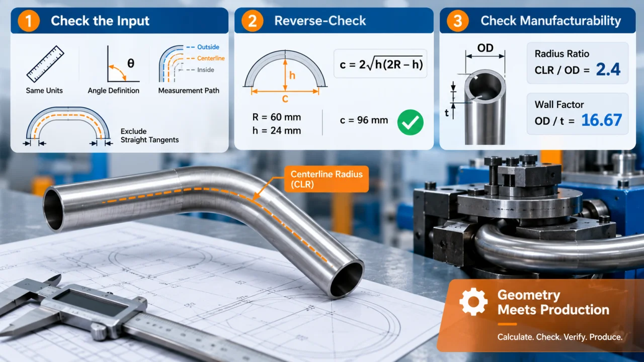
How to Check Your Bending Radius Calculation
Check Units, Angle Definitions, and Measurement Paths
Before you accept a bending radius calculation, review the inputs:
- Put lengths in one unit system. In the sagitta formula, both c and h must use the same units.
- Identify θ as the angle swept along the circular arc. A drawing may show the supplementary angle between the straight legs instead; inspect its dimension convention.
- Confirm that every measurement belongs to the same path: inside, centerline, or outside.
- Exclude straight tangents from an arc-length measurement.
Record these definitions beside the bending radius calculation. A colleague or tooling supplier can then check the dimensions and units without guessing your assumptions.
Reverse-Check the Result and Allow for Measurement Error
You can check a bending radius calculation by rearranging the same geometry to recover an input. For the chord-and-sagitta example:
c = 2√[h(2R − h)].
Substitute R = 60 mm and h = 24 mm:
c = 2√[24 × (120 − 24)] = 96 mm.
The result matches the original chord, so the arithmetic is consistent. However, this check cannot detect a measurement from the wrong surface.
To check how measurement error affects your bending radius calculation, keep c at 96 mm and change h from 24 mm to 23.5 mm. The radius becomes approximately 60.77 mm as a result. That difference comes from a hypothetical input change rather than a recommended tolerance.
For an existing part, record the measurement locations and tool resolution. Repeat measurements over several spans so that you can check whether one circular arc describes the profile. If the calculated radii disagree beyond the measurement uncertainty, investigate the profile and measurement method before reporting one radius. A non-planar bend, on the other hand, needs more geometric information than a flat profile measurement provides.
Can the Calculated Radius Be Produced on a Tube Bender?
Use CLR-to-OD Ratio and Wall Factor
After the geometric bending radius calculation, record two ratios for the manufacturing discussion:
- Radius ratio = CLR/OD
- Wall factor = OD/t, where t is wall thickness.
For CLR = 60 mm, OD = 25 mm, and t = 1.5 mm, the radius ratio is 2.4 and the wall factor is about 16.67. A description such as “2.4D bend” needs an agreed diameter basis; here it means 2.4 times the specified tube OD.
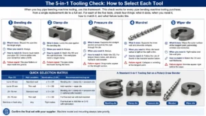
Bend Tooling uses these ratios in its mandrel and wiper selection guidance. The guidance considers material and bend angle as well as the tooling assumptions. Treat the ratios as inputs to an assessment, rather than a pass/fail test for the example tube.
Check Material, Tooling, and Machine Configuration
Ask the equipment or tooling supplier to assess the material grade and condition, OD, wall thickness, required CLR, and bend angle together. Include the complete part drawing so that the review can account for straight lengths as well as adjacent bends.
For rotary-draw bending, discuss the available bend die, clamping arrangement, and any required mandrel or wiper. Ask which tube specifications and tooling configurations the supplier used to establish the machine’s minimum radius, then compare those conditions with your job.
Agree on acceptance criteria before a trial. Specify the dimensions that matter for assembly and any limits on flattening, wall thinning, or surface marks. A bending radius calculation cannot supply those project-specific limits.
Account for Springback and Verify the Finished Bend
The tube can recover elastically after unloading. The amount depends on the bend and material conditions. Swagelok’s Hand Tube Bender Manual, page 19 identifies bend angle, radius, material, and wall thickness as relevant factors and calls for checking the achieved angle.
Use that principle without transferring a hand tool’s compensation setting to a CNC tube bending machine. Confirm the machine’s angle convention and compensation method, then inspect the trial part against the drawing.
Measure the finished geometry that the application requires. Check the radius in addition to the angle, because either dimension can affect assembly. A machine accuracy figure does not, by itself, establish the finished part’s dimensional tolerance.
Frequently Asked Questions About Tube Bend Radius
Can you calculate tube bend radius from outside diameter alone?
No. A bending radius calculation needs information about the curved path as well as any diameter required for conversion. You need additional geometry, such as arc length and angle, or chord length and sagitta. If you are selecting a proposed radius, assess material, wall thickness, tooling, and acceptance criteria before treating that selection as manufacturable.
Does a 180-degree bend have a larger radius than a 90-degree bend?
Not necessarily. Both can have the same radius. At equal radius, a 180° circular arc has twice the length of a 90° arc. The angle specifies how far the arc extends around its circle rather than determining the circle’s radius.
Should you use tube OD or ID in a bending radius calculation?
Use OD when converting between the inside bend radius, CLR, and outside bend radius using the equations in this guide. Arc-and-angle or chord-and-sagitta methods do not require a tube diameter to find the radius of their measured path. Tube ID describes the bore and must not replace OD in the surface-to-centerline conversion.
Can you use nominal pipe size instead of actual outside diameter?
Check the pipe’s dimensional specification first. A nominal pipe-size label is not necessarily its physical outside diameter. Use the specified actual OD for the geometric conversions in this guide. When interpreting a supplier’s D-based designation, confirm which diameter convention the supplier uses.
Is centerline arc length the same as the required tube cut length?
Centerline arc length describes the curved section’s geometry. A complete blank also involves the straight sections and the production method. Establish the required cut length using the part dimensions, applicable process allowances, and trial results. Do not treat one arc-length result as a validated production cut length.
What to Send ZR Tube Bender for a Bending Assessment
Include your bending radius calculation with the drawing so the discussion starts from a defined geometry. State whether the result refers to the inside surface, centerline, or outside surface, and whether it comes from a drawing or a measured part.
For a tube bending engineering assessment, prepare:
- Material grade and condition, tube OD, and wall thickness.
- Target CLR, bend angles, and straight lengths between bends.
- A complete drawing showing bend directions and critical dimensions.
- Dimensional tolerances and permitted deformation or surface marks.
- Expected production quantity or cycle requirements.
Send these details to ZR Tube Bender to discuss a suitable machine and tooling configuration. Ask for confirmation of the applicable conditions before selecting equipment for the proposed radius.